Jason M.
Amazon Echo
DIY Amazon Alexa using a Raspberry Pi 3. This project was made to function just like a regular Amazon Alexa but a more cost-efficient version. This Alexa can respond to voice commands and also includes a self-made amplifier circuit which allows a user to play music via Bluetooth from your phone.
Engineer
Jason M.
AREA OF INTEREST
Electrical Engineering
Software Engineering
SCHOOL
Lowell High School
Grade
Incoming Junior
Reflection
The experiences I had here taught me many different aspects of learning. All the instructors here are really helpful and kind when it comes to something I am stuck on. They try to give you little clues to help you but they really emphasize self-teaching and the ability to figure things out by yourself. While I was here I learned how to use the command line, how to build an amplifier, how potentiometers work, and much more. The project I built allowed me to experience different fields of engineering like mechanical, electrical, and software. Currently, I am trying to transpose the amplifier circuit onto a printed circuit board but this proved to be very challenging because of the complexities of the circuit. What I plan to do next is to continue building a wooden speaker container to hold all these components. In the future, I hope to explore the field of software engineering more deeply.
Modifications
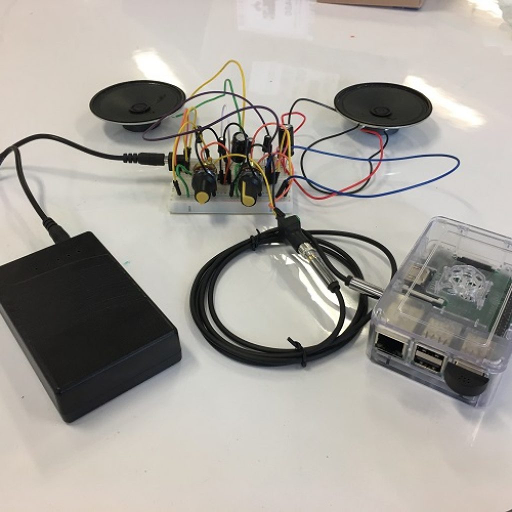
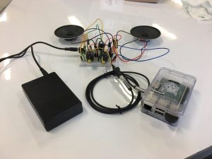
I made an LM386 op-amp circuit so I could amplify the audio signal from the Raspberry Pi to a strength that can be compatible with the speakers. I had to do a lot of research because there were many different circuits that were not compatible with what I was trying to do. I used 2 LM386 op-amps because a single IC can power only one 1 watt speaker. I also used 2 potentiometers which are variable resistors that limit the amount of current passing through them when you turn the knob. This allows me to use them in the circuit as volume knobs. I added some 1000uf capacitors that make sure that there is no DC voltage going into the speakers and damaging them.
A problem I had while making this was when I was testing it out. It sounded really scratchy and bad. After looking at the oscilloscope I saw that there was a lot of other noise. To solve this I added 0.1uf capacitor which filters out the high frequencies and sends them to ground.
Another problem I had while making this amplifier was when there was still a lot of noise even after adding the 0.1uf capacitor. I soon realized that this was because of the diode I added to prevent the DC voltage from going backward and damaging the Raspberry Pi. I replaced this diode with another 100uf capacitor which also prevents DC voltage from going to the Raspberry Pi but also does not interfere with the audio signal as much. Currently, I am trying to transpose the amplifier circuit onto a printed circuit board but it has proved to be very challenging because of the complexity of the circuit.
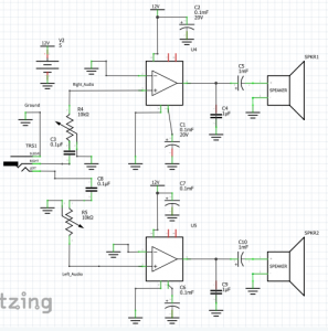
Amplifier Schematic
Modification
Final Milestone
I started by using Alexa Skills Kit on the Alexa Developer app to create a new skill. I then made a new skill called owner information. I proceeded to make a AWS Lambda account to create a function for my skill. I used a blueprint called “alexa-skills-kit-nodejs-factskill” which is a premade function that can be used to ask alexa for random space facts. I then changed the name of the skill to “Owner Information” and added facts about myself to replace the space facts that Alexa would say.
Afterwards, I connected my Alexa skill to my Lambda function by using the Alexa skill ID and the Lambda function ARN or acquirer reference number. I finally tested the skill in Alexa Skills Kit by asking Alexa to “open Owner Information” It responded by giving me a random fact about myself. Now that I am complete with the base project.
I plan to get some speakers and build my own amplifier which is going to amplify the sound coming from the Raspberry Pi enough for it. I also want to put this setup into a container that looks presentable.
First Milestone
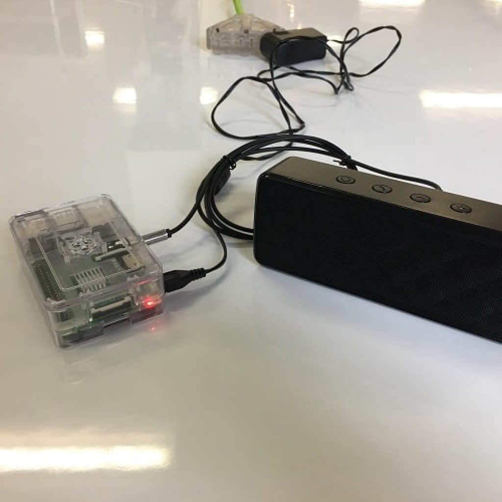
Today I finished my first milestone which was to get Alexa onto the Raspberry Pi. For my main project I decided to build my own Amazon Alexa using a Raspberry Pi 3. I downloaded NOOBS, an operating system installer that contains Raspbian, onto an 32GB SD card. Raspbian is an operating system for those who are new to using a Raspberry Pi and provides a simple easy to use interface. I then installed Raspbian on the Raspberry Pi using the SD card.
I later made an Amazon developer account to add my Raspberry Pi as an Alexa device. I from there on used SSH (Secure Socket Shell) so I could access the Raspberry Pi’s from my laptop. I then downloaded source code from github made by Erik a Technical Writer for Amazon Alexa onto the Raspberry Pi.
Finally I had to run three separate commands in three separate terminals. The first command was used to bring up a web service which is used to authorize my sample app with Alexa Voice Service. The second command was used to run the sample app which communicates with Alexa Voice Service. The third and last command was used to run the wake word engine which allowed me start an interaction with Alexa using the phrase “Alexa”.
Alexa
Starter Project
For my starter project I decided to build the Rainbow Light Show. For this project, I soldered components like a transistor which turns on and off the current. Added IR sensors which determine how bright the LEDs light up. The IR LEDs on the sensor shoot out a beam of infrared light which reflects off your hand into the phototransistors. These phototransistors determine how much current is allowed to go through based on how much light is exposed to the phototransistors. This current is then read by the IC which determines how bright the LEDs should light up. The higher the current the brighter the LEDs.
I also added resistors which will limit the amount of electrical current to certain parts of the board. A 220uf capacitor and two 0.1 capacitors were added to store energy and smooth current fluctuations. Finally a reset button was added so the IC so it can adjust to the light already in the room. This solves the problem of the LEDs lighting up randomly without your hand above the sensor.
One problem I ran into while building the Rainbow Light Show was getting all the components in place and flush against the board to solder them on. This problem was somewhat fixed by using tape. Another problem I had was that an IR sensor responsible for the color red was not working. I discovered that it was a problem with the sensor by holding an android camera to the sensors to check if there was an infrared light coming from the IR LED. What I saw was that the emitter for the green and blue IR sensors were working fine but the red IR sensor was not on. From this I concluded that the sensor was broken.
Rainbow Light Show

Parts


Amplifier Schematic
Modification