Hi my name is James. I am a rising Junior at Cardinal Hayes High School. As you will see in my videos and documentations below I have done during my time at BlueStamp Engineering I have came from a person with no knowledge of anything of engineering to a person that knows and understand more of what an all day engineer does. The projects I have completed were the Electronic Dice Kit and a PS2 controlled Omni-Directional robot. I have learned a lot of things that I never thought I would understand. I thank all my instructors and fellow peers that have helped me to complete these projects and that gave me an awesome experience that I will never forget.
![IMG_1006[1]](http://bluestampengineering.com/wp-content/uploads/2015/06/IMG_10061-300x225.jpg)
Figure 1. My finalized Omni-directional Robot
Code: Official_Omnidirectional_Robot
Schematic:

Final Milestone
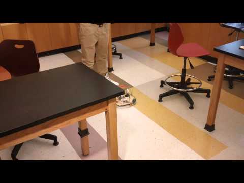
I have a complete Omni-directional robot that is controlled by a PS2 controller. I have also added modifications to make it unique from other Omni-directional robots. The modifications I added to my robot was laser tag and LED’s that light up Green when going forward and Red when going backward, as you can see in the video below. I also coded the laser tag to when my robot is hit by a laser or light it stops completely. It wasn’t as difficult as I thought to do these modifications. The only problems I ran into was where to find it, how to connect it to my Arduino, because I didn’t have space, and getting it all working. Also my problem that I have still is that I couldn’t figure out what causes my Arduino to restart and stop my robot for a second when I press the L1 or R1 button on my PS2 controller. But overall I am happy and satisfied that I have a complete working Omni-directional I can control.

Milestone #2
I have done a lot of work since my 1st milestone. I have made a base and I have put all the components on top of my base. Later on I decided to use metal bars to put a barrier around the base, similar to what bumper cars have. I did this because a peer who sits next to me and is working on the same project as and I decided to ram our robots into each other such in a ‘battle’. Unfortunately, I lost to him because one of my wires was not very secure. Later on I decided to put a dome-like structure to protect my wires and connections from being run over and trampled by rival omni-directional robots. Those were my structural modifications. Then my instructor Kevin asked me what other modifications I wanted to add to my robot and suggested laser tag. This modification consists of a photo diode, an LED, a 3k resistor, and a buzzer. The photo diode is sensitive to light and I coded it to react to light, in this case a laser, hitting the photo diode so that it would trigger the LED to light up and the buzzer to beep for a second. This was not as easy as I thought. It toke me a while to find the parts and figure out how to connect it to my Arduino. I found a very easy and very helpful video that showed me how easy it is to make this (link below). But after combining my code with the laser tag code I ran into a problem that I never thought would happen. My robot stopped working! It took at least 2 days to figure out what it was. I found the problem, and it was that my ground connections on my perf board weren’t soldered properly and I had to re-solder one of the wires. That solved my problem of my robot not working. But as you see in the video my robot stopped at one point when it was turning clock wise and counter-clock wise and I currently do not know what is causing that. Hopefully I figure that out soon and fix it. But other then that I have a complete working omni-directional robot. I will still modify it by modifying my laser tag code such that when the photo diode is hit by a laser the robot will stop completely. See it in action below:
Website where I found the code and schematic for my laser tag modification:
http://www.instructables.com/id/The-2-Minute-Laser-Target-Circuit/
Milestone #1
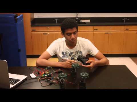
I have completed my first milestone which was to program a PS2 controller via Arduino to control all three Vex motors, a huge step towards a completed Omni-Directional Robot. I programmed the gamepad buttons to make it go forward with the up button, backward with the down button, left with the left button and right with the right button. I also programmed the R1 button to make the motors all go clock wise and the L1 button to make the motors all go counter-clock wise.
I had ran into problems along the way. I had no prior knowledge of programming or robotics, and as a result I was had no clue what or how to start my main project. How I resolved this problem was by doing a lot of research on Arduino code. I found a great tutorial on how to use Arduino. Then I got some help from one of my fellow peers who had more experience and more knowledge of coding. He helped me figure out how to make one motor go in one direction continuously and I figured out how to make all three go forward and backwards on a delay. Then later on I programmed the PS2 controller to make the motors start and stop. The video below shows the motors in action:
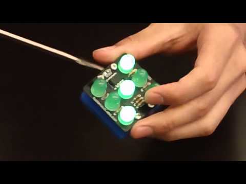
Starter Project
I have completed my starter project of the Electronic Dice Kit. I had to use components such as a PCB, resistors, diode, LED, PIC chip, battery holder, battery, piezo sensor, and the acrylic base. A PCB is an abbreviation for Printed Circuit Board which is a board that supports and electrically connects electronic component using conductive tracks and pads. Resistors are what reduces the flow of energy through the PCB. A PIC chip is like the brain. A piezo sensor is a device that measures changes in pressure, acceleration, temperature, strain or force and converting them to an electrical charge. The Electronic Dice works as I tap the bottom of the acrylic base with my finger or on the table and the piezo sensor is attached to the top of the base, the sensor reads the energy of the impact and the signal goes through the diode and buffer the energy going through it offering some protection to the sensitive PIC chip from an excessive voltage. The PIC chip reads this and as the LED is connected with the resistors, the PIC then sends the signal to these resistors through the LEDs making them light up randomly.