
Hi! My name is Isabelle, and I’m a rising senior at Saint Ignatius High School. I discovered BlueStamp when they appeared at a summer program fair at my school. I was immediately drawn towards the program because it provided an opportunity to put my interest in engineering into action. I chose the “Gram Piano” as my starter project and a small robotic arm as my main project.
I chose to build a robotic arm as my main project because it seemed to be a good introduction to mechanical engineering and coding. I have always had an interest in engineering, however, it was something I had never done before. Building technology and electronics fascinate me, so Bluestamp was the perfect hands-on opportunity to create something. My project was fairly frustrating, however, I was able to get past the problems that occurred and accomplished all my intended modifications. Overall, I enjoyed building the arm and adding code, despite my difficulties. I hope to create more motor based and mechanical projects with the new skills I have gained through this program.

Final Video
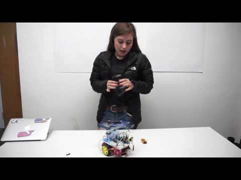
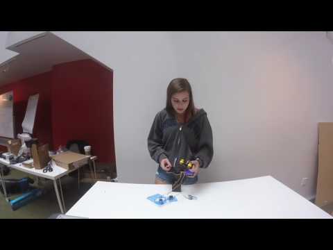
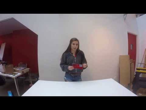
Once I completed my initial project plan, I began to work on modifications. My first modification was to switch to an Arduino and PS2 controller instead of the ‘brains board’ and joystick that the parts came with. By changing boards I would have to change the entire code and transfer wires. I was nervous because I would have to take apart work I had spent hours completing, and I would have to begin writing my own code. I was able to transfer the wires with no problem and writing the code was easier than I had thought it would be because the PS2 library provided an understandable platform to work off of. When I was adding movement commands into my code, I decided to make the arms move in increments of 10 degrees so that they would not immediately go from the initial to final position when I press the button. My second modification was to add wheels. Fortunately, there already was a base with wheels available, so I just had to write the code and connect the wires.
if(ps2x.ButtonPressed(PSB_RED)) { //will be TRUE if button was JUST pressed if(pos1>0) {
pos1-=10;pos2+=10;
}
myservoright.write(pos2);
myservoleft.write(pos1);Serial.println(“Circle just pressed”);
Serial.println(pos1);
Serial.println(pos2);
}
if(ps2x.ButtonReleased(PSB_PINK)) {
if(pos2>0){pos1+=10;pos2-=10;
}
Incremental movement

Second Milestone
I accomplished my second milestone by completing the arms of my robot. They are operated by two micro servos. The servos spin and cause the mechanical parts to move according to the joystick movements. I experienced problems with the servos because the arms would jerk and move with flinches. By using an oscilloscope, a device that displays voltage as a function of time, I was able to see the glitches in signal and voltage drops. The problem was within the code, and when I took out all the code for the LED panel and reloaded it, the arms no longer would glitch. The LED panel was problematic because a line in the code for it required pins that were already in use. Therefore, there was an interference because the pins that were supposed to be in use for the claw were also being signaled to work the LED screen.
First Milestone
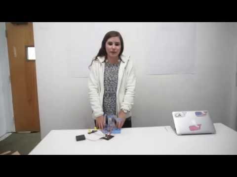
My first milestone was putting together the “Brains Board” and adding the code to the Pro Micro. I first had to plug the micro servos, power source (battery pack), and controller connector into the circuit board. I then connected the Pro Micro into my computer so that I could add the code. I used the Chrome extension Codebender to access and input the code that works with my project. I ran into difficulty when I tried to upload code onto the device because there was an ‘error’. In one of the lines of the code 5 arguments were required, however, only three were put in. I solved this problem by opening the code to edit and adding two more arguments. The code allows the joystick controller to operate the direction of spin within the Micro Servos which will be the source of movement in the robot.

The “brains board” schematic
Starter Project
The SparkFun Gram Piano is a device that uses capacitive touch keys to play notes of different pitch. The capacitive touch keys hold build up and hold a charge until a finger touches the key. I built the project by soldering all the components to the circuit board. Two double A batteries power the circuit. The power switch allows the current to flow from the batteries and through the circuit, and the LED lights indicate that the piano is on and works. The electricity goes through to the board to power the capacitive touch sensors which, when touched, play a note out of the speaker. There are 330 Ohm, 10k Ohm, and 2m Ohm resisters that limit the flow of current. The current from the touched keys goes through the microcontroller which signals the speaker to produce the corresponding tone. The pitch can be changed by turning the potentiometer, which is an adjustable resistor. After completing the project, I turned the switch on; however, the lights did not light up and the project was not functioning. It turned out that one of the battery clips was not in contact with the battery. I pressed the clip in a bit and the project began to work.