Smartphone Controlled Door Lock
I have created a door lock that can be unlocked from anywhere in the house using just a smartphone. Perfect for anyone who is either too lazy or physically unable to get up and open the door.
Engineer
Isaac L.
Area of Interest
Computer Science,
Electrical Engineering
School
Monta Vista High School
Grade
Incoming Junior
Reflection
This project was really important to me as I have not had any real hands-on engineering experiences before. Ultimately, it ignited my passion for both engineering and computer science. I encountered numerous struggles during these past six weeks, but these experiences were all great learning experiences. Learning about facial recognition has sparked my interest in computer vision and trying to convert code between languages has exposed me to new, interesting languages that I will continue to explore. With the knowledge that I gained here at BlueStamp, I will definitely continue to build engineering projects. My main goal would be to try and combine computer science with mechanical and electrical engineering to target the minor annoyances we experience in our day to day lives.
Final Milestone
Final Milestone Images
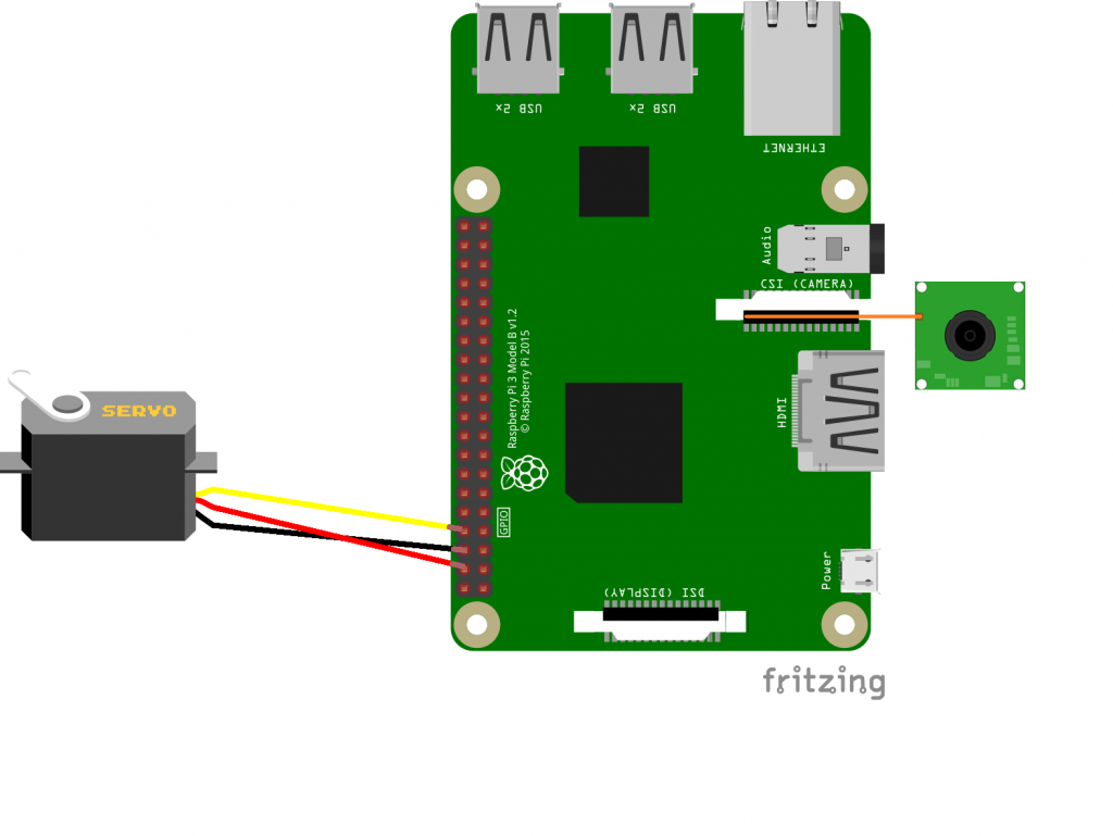
Schematic

For my final milestone, I modified the project by adding a new feature: facial recognition. My only hardware modification was the addition of the Raspberry Pi camera module.
My first step for this milestone was setting up OpenCV. This process took several hours, but it was relatively straightforward. Once I set up OpenCV, I attached the raspberry pi camera module to the raspberry pi and started testing the camera. I ran some sample code I found online, but I encounter an error: Assertion Failed. After researching, I solved this problem by typing in sudo modprobe bcm2835-v4l2.
The next step was to set up the face detection. This was a pretty foreign concept to me, so I had to do a lot of research. I ended up utilizing the “Haar Cascade classifier,” which is a common way people detect faces. This classifier was developed with a machine learning approach where a cascade function is trained from a series of positive (with faces) and negative (without faces) images. I did not create my own classifier; instead, I used a pre-trained classifier, from OpenCV.
Once I set up the face detection, I had to generate the dataset that would train the OpenCV recognizer. To do this, I wrote a program that asks the user to enter their ID for the picture. Then, it takes thirty pictures and saves those pictures into a directory.
After I gathered the necessary data, I had to train the OpenCV recognizer. I created another python file for this code. The recognizer I used was the LBPH (Local Binary Patterns Histograms) recognizer. With two arrays containing all the faces and their respective IDs, I used recognizer.train() to train the recognizer. Once the recognizer is trained, the program writes the model into a .yml file. For any face that I want to add, all I need to do generate the dataset and train the recognizer.
The last step was writing the code that would actually recognize my face and enable me to control the door lock. In my code, I essentially created an infinite loop that would repeatedly detect the face and use recognizer.predict() to return the ID of the person (as a number) and the confidence level. If the person is recognized, they can choose to open or close the lock by pressing the space bar. If the person is not recognized, the ID would become “Unknown,” and they would not be able to open or close the lock.
I worked a lot on the code for this milestone, so feel free to view it on my Github.
Third Milestone
Blynk App
My third milestone is making the door lock controllable by a smartphone. To make the phone interact with the Raspberry Pi, I utilized Blynk, a popular app that only requires an internet connection to interact with numerous devices: Raspberry Pi, Arduino, etc.
When I was still controlling the Raspberry Pi through a VNC viewer on the computer, I used Python to code the servo to move. However, the app I used, Blynk, does not support Python yet. As a result, I had to convert the code to NodeJS. This proved to be a difficult task, as I had never worked with NodeJS before. With the help of reference code by someone who had done a similar project before, I was able to write code to control servo the way I wanted to. When I looked at the reference code, I made sure to research the function of each line and what everything does.
While writing and running my code, I encountered several challenges. Because I was completely new to NodeJS, I had to spend a lot of time researching and learning about how to work with NodeJS. On my Raspberry Pi, I had to install numerous packages with the command npm install. During the process of installing all the necessary packages, I ran into permission errors which prevented the installs from happening. Sometimes, using sudo before the command worked; however, sometimes it did not work. This process was quite frustrating because I felt as if I was making no progress. After many hours of research and running different commands like sudo apt-get update and sudo node-gyp rebuild, I was finally able to get my code up and running.
In achieving this milestone, I learned about NodeJS and about the node modules and packages needed to make my code work. The two modules that I used were the blynk-library and pigpio. In addition, I learned how to write basic code in NodeJS.
Feel free to take a look at my code for this milestone, which can be found on my Github.
Second Milestone
Milestone 2 Images
My second milestone consists of attaching the servo to the actual lock. This is essentially the final layout for the door lock, as I do not have a physical door to mount the lock on. In achieving this milestone, I was able to learn about and work with Dremel tools.
In order for the servo to actually fit on the lock turning rod, I had create a special servo-plate. To create the servo-plate, I worked with power tools to create a hole that fitted my needs. During this process, I ran into a few difficulties. Although I was able to get the the servo-plate to fit on the turning rod, I found that the plate was too large. To attach the base to the rest of the lock, two screws are used; however, those screws restricted the movement of the servo. To solve this, I had to use the power tools once again to reduce the diameter of the circular servo-plate.
After I successfully made a servo-plate that would fit on the lock turning rod, I needed to mount the servo to the base of the lock, otherwise the servo would move instead of the actual lock. I did this using both super glue and hot glue, as super glue itself proved to be insufficient in terms of strength.
First Milestone
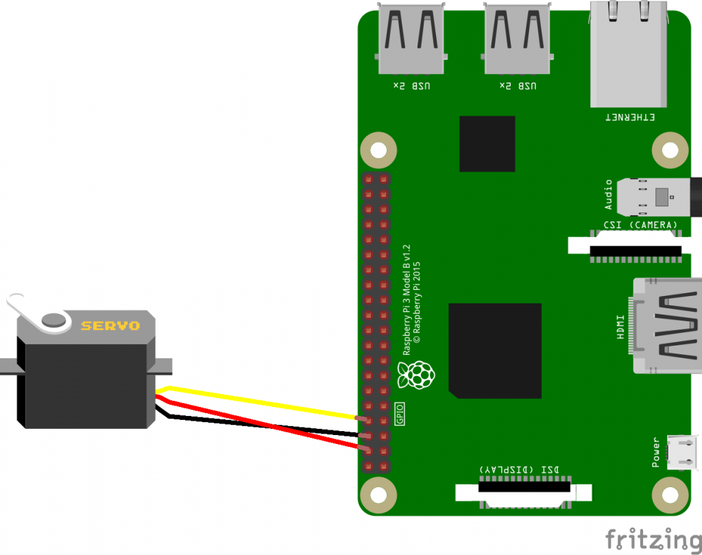
Schematic


