3D Printed Hand

My project is a 3d printed hand that is controlled with your hand (with a glove on). Flex sensors are attached to the glove and when you bend your fingers, the flex sensors send a signal to the hand to bend

Engineer

Isaac

Area of Interest

Architecture

School

Ramaz

Grade

Incoming Sophmore

Reflection

When I started bluestamp, I had low expectations for learning a lot while just making one project, but my expectations were very wrong. I believe what made me learn a lot was not making the project itself, but encountering problems was what actually made me learn so much. I will hopefully be applying the knowledge I acquired here and working on projects in the future. I will possibly add a pressure sensor on the palm, and make the hand and glove wireless.

Final Milestone

I finished my final milestone: getting the robot hand to move the same as my hand. The way this works is when the servos move (explained in the previous milestone) they pull strings that are wrapped around the fingers to pull them up or down.  When I put together the 3d printed parts, I encountered some problems. For example, some joints would not move because the fingers were rubbing on each other. I fixed this issue by filing down some parts so they would not be touching each other.  Another small problem was that the fishing wire was too thin to pull the fingers up and down. The fishing wire would slide through the fingers, resulting in no motion with the fingers. I resolved this problem by putting hot glue on the fishing wire on the tip of the fingers so it would not slide through the finger as you can see in figure 3. The main problem  was there was a delay whenever I tried to move the hand. I would bend the fingers and then it would stop for a couple of seconds and then go back into its original position. I did many things to try to fix this problem and I got very frustrated. Then, I just realized that the servos need a separate power source than from the Arduino. Finally, my project was working as expected. One thing I have learned in the process of reaching this milestone is that you will always encounter a problem when you are working on a project. A lot of the time you will have to find your own solutions based on your logical reasoning and creativity.

Second Milestone

For my second milestone, I constructed and assembled the 3D printed components of my hand. The first thing i had to do was screw together the 3d printed parts together and screw the servos into the forearm. The process of putting the fishing wire on the servos was by far the most tedious part of making the prosthetic hand. The thing that made me so frustrated was tying the strings tight enough so the fingers would be able to move freely. Also the fishing wire was too thin and when the servos would be pulling it the fingers would not move because the fishing line was just sliding through it. Another reason for this issue is because the joints were too close together and there would be friction between the joints and they would not move smoothly enough and only one joint in each finger would bend. I resolved this large issue by adding hot glue on the tip of my fingers so the fishing line wouldn’t slide, and i disassembled the fingers and filed down where there would be friction so there is space between them. Something i learned in the process of reaching this milestone was that you will always encounter problems, and you have to think of your own way of figuring the problem.

Assembly for the hand:

http://theroboarm.com/overview.html

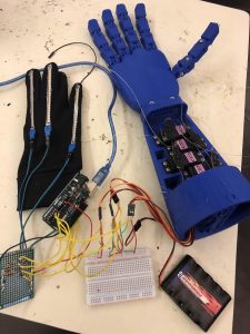
Figure 1: whole project

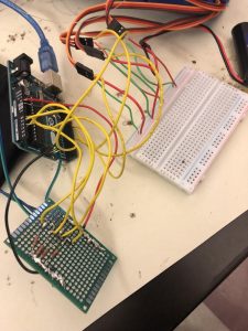
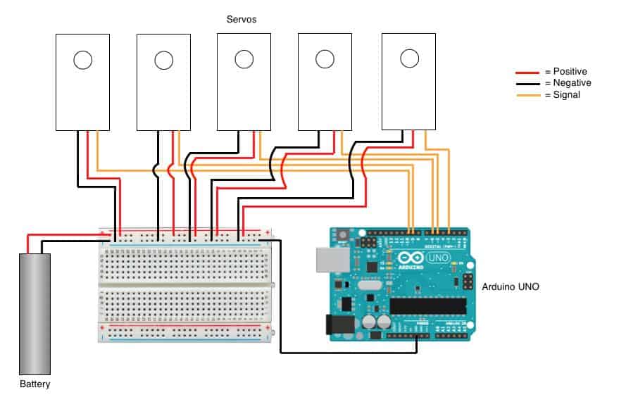
Figure 2: wiring; flex sensors connection on bottom and servos connection on right

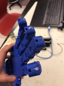
Figure 3: Solution to issue I had with fingers not moving.

First Milestone

This milestone is testing the servos with the flex sensors. I programmed the servos to spin proportional to the amount the flex sensors flex. Flex sensors are variable resistors. When the flex sensors are paired with normal resistors and bent, a change of resistance can be sensed by how much the sensors are flexing. I created a voltage divider where the voltage varies with the resistance of the flex sensor. In Figure 1, the equation for Vout is Vout=Vin( R2/(R1+R2) ), Therefore, as R2 goes up, voltage (Vout) goes up. The way the resistance can be measured is when the microcontroller interprets the ADC value into resistance. In the code, when the flex sensors are connected to the pins and then flexed, the program reads the resistance of the flex sensors.  Once this happens, the code then tells the servos to move proportionally to the resistance of the flex sensors. I programmed it so that past a certain threshold of resistance the servos wouldn’t move past that limit. I encountered many problems in the process of reaching this milestone like bugs in my code and wrong wiring. When I ran into a certain problem, I learned about that specific problem so it was easier to solve. Things I will work on more is to fix the range of the servos moving because some of them are moving more than others. In the process of reaching this milestone, I learned a lot about coding with Arduino and circuits in the STEM summer camp. The website I found the schematics from http://www.instructables.com/id/DIY-Robotic-Hand-Controlled-by-a-Glove-and-Arduino/ The website about the voltage divider rule: http://www.instructables.com/id/DIY-Robotic-Hand-Controlled-by-a-Glove-and-Arduino/
Code for testing flex sensors with the servos

//Define sensors and servos

#include <Servo.h> //Includes servo library

Servo finger1, finger2, finger3, finger4, finger5;

int servoPin1 = 5;
int servoPin2 = 6;
int servoPin3 = 9;
int servoPin4 = 10;
int servoPin5 = 3;

int flexPin1 = A0;
int flexPin2 = A1;
int flexPin3 = A2;
int flexPin4 = A3;
int flexPin5 = A4;

void setup()
{
//Attach the servo objects to their respective pins
finger1.attach(servoPin1);
finger2.attach(servoPin2);
finger3.attach(servoPin3);
finger4.attach(servoPin4);
finger5.attach(servoPin5);

/* set each servo pin to output; I’m not acutally sure if this is
even necessary, but I did just in case it is */
pinMode(servoPin1, OUTPUT);
pinMode(servoPin2, OUTPUT);
pinMode(servoPin3, OUTPUT);
pinMode(servoPin4, OUTPUT);
pinMode(servoPin5, OUTPUT);

//Set each flex sensor pin to input: this is necessary
pinMode(flexPin1, INPUT);
pinMode(flexPin2, INPUT);
pinMode(flexPin3, INPUT);
pinMode(flexPin4, INPUT);
pinMode(flexPin5, INPUT);

}

void loop()
{
//Defines analog input variables
int flex1 = analogRead(flexPin1);
int flex2 = analogRead(flexPin2);
int flex3 = analogRead(flexPin3);
int flex4 = analogRead(flexPin4);
int flex5 = analogRead(flexPin5);

/* Defines “pos” variables as being proportional to the flex inputs.
The 400 to 700 value range seemed adequate for my sensors, but you can change
yours accordingly. */
int pos1 = map(flex1, 400, 700, 0, 180);
pos1 = constrain(pos1, 0, 180);
int pos2 = map(flex2, 400, 700, 0, 180);
pos2 = constrain(pos2, 0, 180);
int pos3 = map(flex3, 400, 700, 0, 180);
pos3 = constrain(pos3, 0, 180);
int pos4 = map(flex4, 480, 640, 0, 180);
pos4 = constrain(pos4, 0, 180);
int pos5 = map(flex5, 400, 700, 0, 180);
pos5 = constrain(pos5, 0, 180);

//Tells servos to move by the amount specified in the “pos” variables
finger1.write(pos1);
finger2.write(pos2);
finger3.write(pos3);
finger4.write(pos4);
finger5.write(pos5);
}

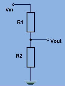
Figure 1: Voltage Divider Rule

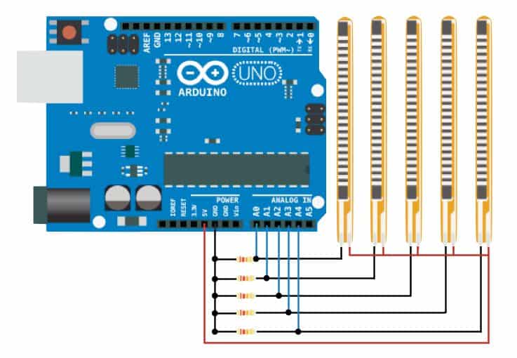
Figure 2: Flex Sensor Schematic

Figure 3: Servos Schematic

useless machine

For my starter project, I built the Useless Machine. The following is the sequence for the Useless Machine: 1) When the toggle switch is flipped, the motor spins one way and the LED turns on in the green color, 2) the actuator flips the switch back, the LED turns red,3) the motor spins the actuator until it touches the limit switch, resulting in the motor and LED to turn off. This device contains an actuator which is driven by the motor and is triggered by 2 switches, the toggle switch and limit switch. When the limit switch is pushed, the mechanism is off. So when the machine is not in action, that means that the actuator is pushing on the limit switch. Because there is strength needed for the arm to flip the switch back, A gear motor is being used, which helps increase the torque but also reduces the speed. This whole contraption is powered by triple A batteries. When I started this project, I thought it was going to be really easy and I also thought that I would not be intercepted by any obstacles. That was not the case at all, in fact, the opposite of what I expected happened. When I started building the project, it was easy and I built most of it, and when I tried it, the motor was going the opposite way and the LED was orange. The whole next day was spent trying to fix what it was supposed to do. I used trial error and applied logical reasoning to fix this, like switching wires to get the motor spinning a specific way, or soldered some things on better. I was very satisfied when I finished this and I feel like I have learned a lot about building this project in the Bluestamp STEM summer camp.

Leave a Comment

Start typing and press Enter to search

Bluestamp Engineering