
My name is Ian and I’m a rising junior at San Francisco Waldorf High School. I applied to BlueStamp because I love building things, and I want to study engineering in college. I hoped that my time in this program would narrow down what kind of engineering I want to study and if I really want to study it at all. Before I started the program I thought that I might want to study mechanical engineering but now I think I might want to study electrical engineering as I have found what I learned about electricity to be extremely interesting and challenging and working with the wiring for my projects was the most fun I had in the program.
2nd Main Project NFC Ring Controlled Lockbox
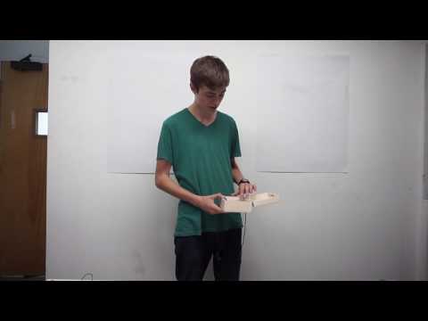
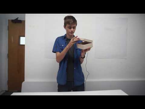
Because I moved through my first project so quickly I started on a second project- An NFC ring controlled lock box. It uses an NFC reader and ring, an Arduino microcontroller, and a servo motor to lock and unlock the box.
Final Video
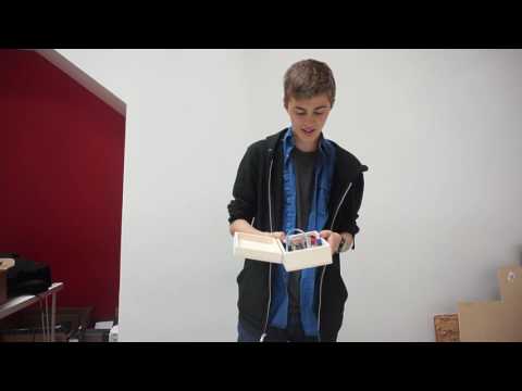
For my modifications I added a piezo buzzer to play the chest opening sound from The Legend of Zelda video game series, and I also added yellow/orange LEDs for when the box opens. For the piezo buzzer, all I had to do was hook it up to the Arduino and copy/paste code I found on the internet into my code for opening the box. The buzzer was slightly too loud at first so I used a resistor between the buzzer and the Arduino in order to turn the volume down.
The LEDs were significantly more difficult. In order to get 6 LEDs to light up with a 5v power source I had to wire them in parallel with a MOSFET. This diagram was the basis for how I wired them.

The MOSFET makes it so the LEDs are powered by the 5v pin of the Arduino as opposed to a digital pin. If the LEDs drew power from the digital pin, it would burn out the pin. With the MOSFET, the digital pin instead only says whether the LEDs should be on or off. For a long time I couldn’t get the LEDs working. I tried many different solutions, none of which worked. The circuit ended up breaking my servo which I had to replace. This persisted for a couple days till we used a multimeter on it to find that I had labeled the positive and negative wires incorrectly. Once fixed, the wiring the LEDs worked fine. I then built a wood cover for all the circuitry to divide the wiring from whatever I put in the box. I drilled holes in the cover for the LEDs.

This is the code I used for the box:
#include “Servo.h”
#include “Wire.h”
#include “PN532_I2C.h”
#include “PN532.h”
PN532_I2C pn532i2c(Wire);
PN532 nfc(pn532i2c);
Servo myservo; // create servo object to control a servo
int pos=1; // variable to store the servo position
int ledPin = 8;
int speakerPin = 0;
const int switchPin = 1;
char notes[] = “azbC”; // a space represents a rest
int length = sizeof(notes); // the number of notes
int beats[] = { 2,3,3,16,};
int tempo = 75;
void playTone(int tone, int duration) {
for (long i = 0; i < duration * 1000L; i += tone * 2) {
digitalWrite(speakerPin, HIGH);
delayMicroseconds(tone);
digitalWrite(speakerPin, LOW);
delayMicroseconds(tone);
}
}
void playNote(char note, int duration) {
char names[] = { ‘c’, ‘d’, ‘e’, ‘f’, ‘g’, ‘x’, ‘a’, ‘z’, ‘b’, ‘C’, ‘y’, ‘D’, ‘w’, ‘E’, ‘F’, ‘q’, ‘G’, ‘i’ };
// c=C4, C = C5. These values have been tuned.
int tones[] = { 1898, 1690, 1500, 1420, 1265, 1194, 1126, 1063, 1001, 947, 893, 843, 795, 749, 710, 668, 630, 594 };
// play the tone corresponding to the note name
for (int i = 0; i < 18; i++) {
if (names[i] == note) {
playTone(tones[i], duration);
}
}
}
void setup() {
nfc.begin();
nfc.SAMConfig();
pinMode(switchPin, INPUT);
digitalWrite(switchPin, HIGH);
pinMode(ledPin, OUTPUT);
}
void loop() {
if(pos==1){
digitalWrite(ledPin, HIGH);
myservo.attach(3);
myservo.writeMicroseconds(2000);
pos=2;
delay(300);
pinMode(speakerPin, OUTPUT);
if (digitalRead(switchPin) == 1) {
for (int i = 0; i < length; i++) {
if (notes[i] == ‘ ‘) {
delay(beats[i] * tempo); // rest
} else {
playNote(notes[i], beats[i] * tempo);
}
// pause between notes
delay(tempo / 2);
}
}
delay(100);
delay(3000);
digitalWrite(ledPin, LOW);
delay(400);
}
if(pos==3){
myservo.attach(3); // attaches the servo on pin 3 to the servo object “Digital 3″
myservo.writeMicroseconds(580);
pos=4;
delay(400);
}
if(pos==2){
myservo.detach();
}
if(pos==4){
myservo.detach();
delay(2000);
}
String ringUid;
boolean success;
uint8_t uid[] = {0, 0, 0, 0, 0, 0, 0}; // Buffer to store the returned UID
uint8_t uidLength; // Length of the UID (4 or 7 bytes depending on ISO14443A card type
success = nfc.readPassiveTargetID(PN532_MIFARE_ISO14443A, &uid[0], &uidLength);
if (success & uidLength==7) {
for (uint8_t i=0; i<7; i++){
ringUid += String(uid[i], HEX);
}
if (ringUid==”4f6fb6aca4880″ || ringUid==”b9ffd92”){
if(pos!=4){
pos=3;
}
if(pos==4){
pos=1;
}
}
}
}
The code uses an if statement to open the box. If the NFC reader reads my ring and the box is locked, it will light the LEDs, turn the servo to the open position, and play the tune.
Milestone 2
For my second milestone I wrote the code for my lockbox. It now toggles open and closed with an NFC ring. In order to do this I had to learn how to use and get used to Arduino. My biggest struggle was getting the libraries to work and trying to deal with problems I didn’t understand with the code. A library is a collection of code that performs functions that relate to each other. I needed the libraries to help the NFC reader communicate effectively with the Arduino. I couldn’t get the libraries to work for quite a while. I had to use a manual for the libraries to get them to work, and I found out that there was a small switch I had to physically flip on the NFC chip. I also had to change a few numbers in the code to get it to work. The other big problems I had seemed to resolve themselves just by rebooting the system. I learned that coding takes a lot of patience, that it will almost never work the first time, and that I have to be okay with that.
Milestone 1
For my first milestone I built the hardware for my lockbox. The only problem I faced was figuring out how to effectively mount the servo so that it could hold down the lid of the box effectively without being removed if you pulled on the lid. This was a problem because the servo is designed to be mounted into a surface with a hole cut out for it instead of being attached to the side of something. I tried many methods of securing it down like duct tape. I ended up 3d printing a servo mount I found on the internet.

I dremeled a slit in the lid of the box for the servo arm to turn into to lock the box. I didn’t have many problems with this milestone beyond this.
1st Main Project: Vertical Axis Wind Turbine Iphone Charger (VAWTIC)
My first project was a wind turbine that can charge a phone. It uses a stepper motor, battery and minty boost to serve as a functioning power source for anything that can be charged by a usb cable.
Final Video
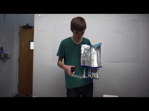
For modifications I added solar panels to my wind turbine.

I simply built a platform for the panels and hooked them up to the charging circuit. I intended to add 3 times more panels than I did but the only way I could cut the acrylic plastic was with a jigsaw and that was extremely difficult, didn’t always work, and the piece created wouldn’t always work. It didn’t feel like I modified this project much, but much like Alex K’s Project a good portion of my project is a modification. The original design was only meant to be a lantern and my modification was turning into a charger.
2nd Milestone:
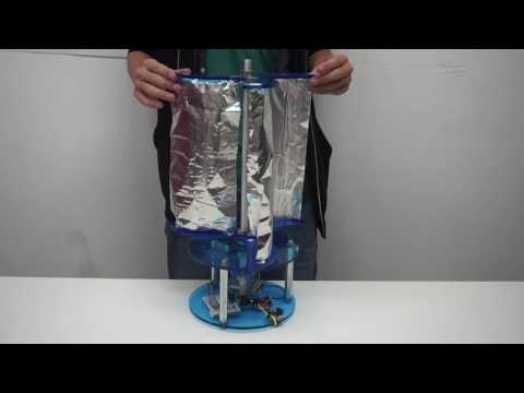
For my 2nd milestone I built the mechanical structure for my project.


I waited a long time for the aluminum rod that makes up the shaft of the turbine to come in. When it did come in it was 6 inches too short. My first solution was to raise the shaft so it only went through one of the holes in the base, giving me more room up top for the sails. This didn’t work as it was too wobbly. My solution for the shakiness was to superglue a shaft bearing to the base to give more stability. This only made things worse as it caused the shaft to no longer spin freely. I had to sand both parts down a lot and apply lubricant to correct this error. I ended up returning the shaft to its original position and accepted the loss of the extra inches from the sail.
The only other problem I faced was when I set the gears in place. Some of the teeth in the gears were too long and prevented the motor from spinning. I fixed this by marking which gears caused problems and sanding them down with a file. When I finished this version of the turbine I tested it outside in the strong winds. I found that the sails were not big enough to turn the motor. I dismantled the project and waited for a new, longer aluminum rod.
The new version with the full sized aluminum rod works.

Milestone #1

For my first Milestone I completed all the circuitry for my project.

What I had to do for this was create a circuit that took the power from my motor and use it to charge a Lipoly battery. Then I had to get the power from the battery to a mintyboost so I could charge a phone. In order to get the power from the motor to the battery I had to use 2 circuits. The first is a full bridge rectifier.

Explanation of a full bridge rectifier: The point of this circuit is to convert the AC (Alternating current) power created by the motor to DC (direct current) power which is taken by the battery. The difference between the two is quite simple. AC or alternating current power means that the voltage switches from positive to negative. For example if you had two wires running on the same AC power they would alternate which was positive and negative. While DC powered wires will not change their charge. See graph below


The point of the full bridge rectifier is to make it so no matter which of the AC powered wires is positive the positive energy always flows to the same place. It does this using diodes which electricity can only flow through in one direction. It also uses a capacitor to stabilize the voltage. See the diagrams below. On the left is AC power being inputted to the bridge, and on the left is the DC power being outputted.
 I first prototyped this circuit using a breadboard and a picture from the instructions I was using. Then once I felt I understood the circuit and tested it to see if it worked, I rebuilt a condensed version of the circuit on a solder board. The charging circuit was a pre-made circuit.
For that I only had to use a multimeter and some diagrams to figure out where the inputs and outputs were. Connected to the charging circuit is a lipoly battery that I intend to replace with a bigger one and a mintyboost which will take the power from the battery and boost the voltage to 5 volts so I can charge my phone using wind power.
Starter project:

For my starter project I built a Minty boost.

The minty boost is boost converter that changes the 3 volts inputted by two AA batteries into 5 volts which is accepted by a cellphone. A boost converter works by the properties of an inductor. An inductor is a coil that has the property that it resists changes in electric current flowing through it. Because of this if the current flowing through it suddenly cuts off it will boost the voltage to compensate. The chip in the circuit is what causes the current to be interrupted. It is programmed to interrupt the current consistently in a frequency that will make it so the inductor is constantly boost the voltage of the power flowing through it to 5 volts. The other circuitry parts are capacitors to stabilize the input and output to make sure they are constant, a diode to ensure that the power only goes one way, and resistors to make sure that everything runs smoother.
The only real challenge I face while making this is that the wires coming from the battery pack are stranded as opposed to coiled or one solid wire. This makes them difficult to work with as they break easily and fray which makes them difficult to fit through the holes.
In working on this project I learned how to solder effectively, what a boost converter and its parts are, and gained a better knowledge of electricity and how it flows through circuits.