The Best Rootin’ Tootin’ Basketball Shootin’ Tracker in the World
My Basketball Shot Tracker uses two PIR sensors positioned at the rim and below the net of a basketball hoop to track the number of baskets made.
Engineer
Ian R.
Area of Interest
Electrical / Mechanical Engineering
School
The Urban School of San Francisco
Grade
Rising Senior
Final Milestone
Video of Shot Tracker Test
Second Milestone
First Milestone
Circuit Schematic

Code
Top Sensor
//PIR Sensor (Top of Backboard)
int ledPin = D0; // Establish pin for the LED
int inputPin = D4; // Establish input pin for PIR sensor
int pirState = LOW; // Assume no motion detected at start
int val = 0; // Variable for reading the pin status
void setup() {
pinMode(ledPin, OUTPUT); // declare LED as output
pinMode(inputPin, INPUT_PULLUP); // declare PIR sensor as input
Serial.begin(9600);
}
void loop(){
val = digitalRead(inputPin); // read input value
if (val == HIGH) { // check if the input is HIGH
digitalWrite(ledPin, HIGH); // turn LED ON
if (pirState == LOW) {
// we have just turned on
pirState = HIGH;
Particle.publish(“Motion_PIR_Top”,”Motion_detected”); //Publish event when motion detected
}
} else {
digitalWrite(ledPin, LOW); // turn LED OFF
if (pirState == HIGH){
// we have just turned off
pirState = LOW;
}
}
}
Bottom Sensor
//PIR Sensor (Bottom of Backboard)
int ledPin = D0; // Establish pin for the LED
int inputPin = D4; // Establish input pin for PIR sensor
int pirState = LOW; // Assume no motion detected at start
int val = 0; // Variable for reading the pin status
int score = 0; // Counter variable for shots made
int other_sensor = 0; // Used for delay between both sensors
int this_sensor = 0; // Used for delay between both sensor
void motion_track_score(const char *event, const char *data){
other_sensor = millis();} //Used to track time of motion event from top PIR
void setup() {
pinMode(ledPin, OUTPUT); // declare LED as output
pinMode(inputPin, INPUT); // declare sensor as input
Particle.subscribe(“Motion_PIR_Top”,motion_track_score); //Subscribe to motion of top PIR
Serial.begin(9600);
}
void loop(){
val = digitalRead(inputPin); // read input value
if (val == HIGH) { // check if the input is HIGH
digitalWrite(ledPin, HIGH); // turn LED ON
if (pirState == LOW) {
this_sensor = millis(); //Used to track time of motion event of bottom PIR
if (abs(other_sensor-this_sensor)<=2000){ //If time between events < 2 seconds, shot is made
score=score+1; //Increment shot counter
Particle.publish(“Basket_Made”, String(score)); //Publish event and shot counter
}
// we have just turned on
pirState = HIGH;
}
} else {
digitalWrite(ledPin, LOW); // turn LED OFF
if (pirState == HIGH){
// we have just turned off
pirState = LOW;
}
}
}
Starter Project: Useless Machine
How It Works
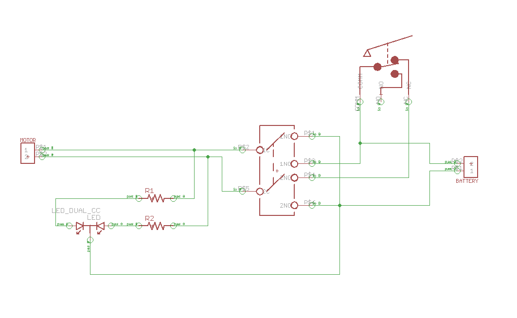
The Useless Machine is composed of 3 main components: the base, the motor with its accompanying arm, and the PCB, or Printed Circuit Board. As you can see on the outside, the base of the machine is the black box, which gives structure and a foundation to the rest of the machine. The other two components work in tandem to make the machine move or work. The machine is given its purpose and basic instructions by the PCB, which features a switch, a snap switch, two resistors (100Ω and 220Ω), a bi-color LED, and a terminal for the wires of the motor and the battery pack that connects them to the PCB. The PCB routes the power from the batteries to the motor arm, with different instructions depending on the conditions of the switch and snap switch. When the switch is initially flicked, the PCB reads this and causes the motor arm to move up towards the switch. The motor arm then flicks the switch back to its starting position, before moving in the opposite direction, and stopping when it comes in contact with the snap switch. The LED flashes a green light as the motor arm moves up, and then flashes a red light when the motor arm moves back down to its starting position.
Schematic