Automatic Plant Watering Device
Hi, My name is Ian. I am a rising sophomore at SAR High School. My project this year is an automatic plant watering device.
First Milestone
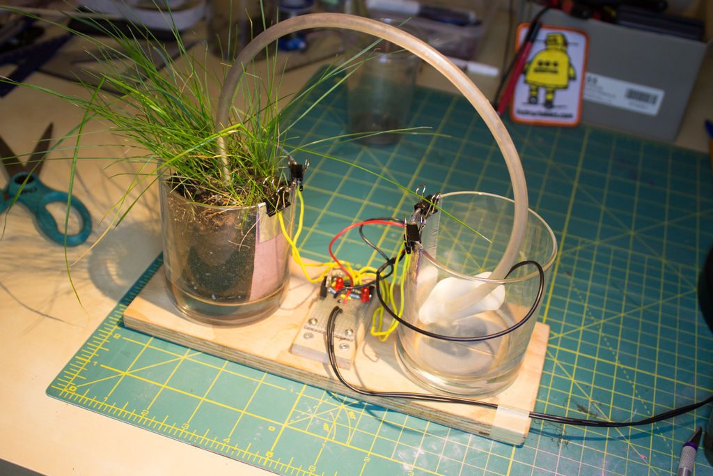
Figure 1: The schematic of my circuit can be seen above
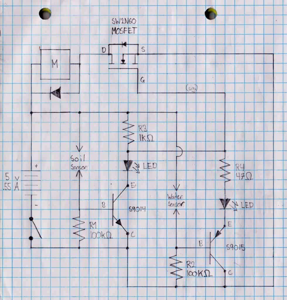
Figure 2: My circuit and both the reservoir and plant bucket can be seen above
Today, I reached my first milestone. I completed the circuit seen in Figure 1 below. To verify it worked fully, I got the water pump to work. For my first milestone, I am testing my circuit on a breadboard before I solder it onto a perfboard as seen in Figure 2 below. Since I am just testing the circuit, I replaced the sensors each with a push button to easily test if the sensors work. The purpose of this device is to water the plant only when the soil is dry. The circuit uses a MOSFET to turn on and off the motor depending on the amount of voltage from the soil sensor. The soil sensor consists of two aluminum foil pieces attached to the sides of the plant pot with voltage going from one side. When there is water in the soil, the circuit is completed between the two aluminum foil pieces since the more water there is, the more current. This voltage from the sensor leads to the gate of the MOSFET. The gate of the MOSFET transistor can control the flow of current between the drain and source depending on the amount of voltage applied. A MOSFET works electronically like a switch. In my circuit, the MOSFET is connected to the pump and sensors. Therefore, the MOSFET closes and opens the channel to supply power to the pump based on the sensors’ state.When the soil is dry, the MOSFET turns the pump on, and when the soil is moist it turns the pump off. My circuit also contains two LEDs which are attached to each sensor. These LEDs are useful when testing the sensor and are great indicators for when there is not enough water in the reservoir or when the soil was watered. The circuit also contains a leaded semiconductor diode to make sure current flows in one direction through the pump. One challenge that I faced was that there are many components to attach onto the board and it could easily be miswired. You have to make sure to triple check that you wired your circuit correctly and that all of the connections are where they are supposed to be. I was able to troubleshoot using a multimeter and an oscilloscope to check the amount of voltage going through the connections between all of the components. It was fun creating and testing my circuit on a breadboard.
The useless machine
My starter project is the Useless Machine by spikenzielabs. The main concept is that when the switch is flipped an arm comes out from inside the box and flips the switch back to its starting position. This is accomplished with a DC motor, actuator, battery pack, a LED, two switches, a toggle switch and a limit switch, and two resistors. When the toggle switch is flipped, the circuit to the LED and motor is complete. This causes the LED to illuminate a green light and the motor raise the arm. LED stands for light emitting diode. Diodes are electrical components that act as one way valves. In an LED when the current flows through this diode, light is emitted in a chemical reaction.When the toggle switch is flipped back it causes the current to reverse, retracting the arm back inside the arm and changing the LED to red. The Useless Machine’s circuit also has a limit switch. This prevents the motor from bringing the arm too far down in the box, hitting the bottom panel. The Limit Switch is wired up so that it’s normally closed, or turned on. When anything pushes the lever, the switch opens, or turns off. This is opposite to how most switches work. When The toggle switch is pushed down it stops the flow of electricity. Therefore, when the arm retracts into the box and hits the limit switch, the current is blocked, turning off the LED and stopping the motor. One challenge that I faced while making the Useless Machine was soldering. I had difficulty soldering some of the components onto the circuit board. I melted a part of my circuit board so I had to redo the entire board. By doing this project I learned how to solder and troubleshoot