
Hi! I’m Holly and I’m a rising senior at the Urban School of San Francisco. This is my first year at BlueStamp. My starter project was a voice changer and my main project is an omnidirectional robot. An omnidirectional robot is a robot that can move in all directions. I based my project off of Rain’s project. This is my first engineering project ever, so I chose a simple project in order to learn the basics of coding and engineering. Watch/read about it below!
I came into BlueStamp having no prior experience with engineering. I have always been interested in robotics, but I have never had the chance to make my own robot. I joined BlueStamp to learn how to build on my own, to learn about all different forms of engineering, to challenge myself, and to determine whether or not I want to pursue engineering in college. After completing my omnidirectional robot at BlueStamp, I realized that my favorite part of my project was the building aspect. I loved taking my ideas and making them into a tangible object. I also enjoyed modifying my robot because it gave it a purpose. It also allowed me to combine my previous knowledge of sound design with my new engineering knowledge. After this experience, I think I want to pursue medical technology in future, because it would allow me to build robots with the purpose of helping people.
Table of Contents
| BOM | Robot Build Plan | Starter Project | First Milestone | Second Milestone | Third Milestone | Omnidirectional Robot Code | Final Video | LED Code |
Final Project

Final Video
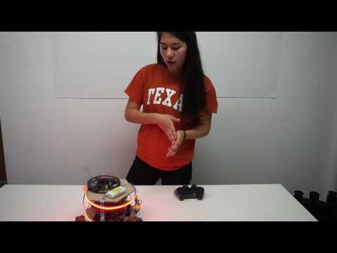
For my final video, I added sound reactive LEDs as a modification to my omnidirectional robot. The key components were a sound sensor and an LED strip. Because the sound sensor is a microphone, it can pick up sound. I connected my microphone to an analog pin on my Arduino, which allowed my Arduino to read varying volumes of sound, as opposed to a digital pin, which can only read amplitudes as either high or low. Next, I connected my LED strip to my Arduino. I coded my Arduino to turn the LEDs to a specific colors at specific volumes. Therefore, my LEDs are sound reactive because at different volumes, the LEDs will show different colors. Finally, I combined my omnidirectional robot code with my sound reactive LED code to complete my robot. However, this was my biggest challenge because the first time I combined my code, the LEDs worked, but the motors moved on their own. After examining my code and finding no errors, I read online that servo motors and Adafruit Neopixel LEDs are difficult to run together. On an Arduino Uno, Adafruit Neopixel LEDs can only work with servo motors if the motors are plugged into pin 9 and/or 10. However, I have three servo motors and require three pins to maintain my robot’s omnidirectional movement. Because the issue involved the servo library being incompatible with the Adafruit Neopixel Library, I re-coded my LEDs using the FastLED library, but this still did not fix the issue. Finally, I fixed the issue by opting for two Arduino Unos: one for my LED code and one for my omnidirectional code.
Milestone 3
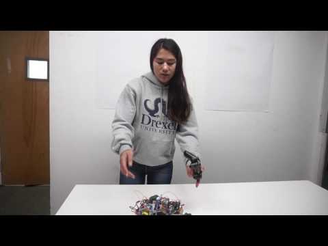
For my third milestone, I coded my robot to move omnidirectionally with the left analog stick. Originally, I coded my robot to move in certain directions depending on the x and y coordinates of the joystick. However, this code limited my robot to only eight directions: forwards, backwards, right, left, and diagonally in four directions. I coded the different directions using a guess and check method, but this caused my robot to move in different directions at different speeds. I also did not use the map function, which interprets how far the analog stick is moved from the origin to determine the magnitude of the motors. I was not happy with the movement of my robot, so I looked at Max’s page to see how he coded his robot. After reviewing his How I figured Out Directional Wheel Code document, I discovered that there was way more trigonometry involved in coding the wheels. Using the analog stick, I coded my robot to move at an arbitrary angle theta using atan2(y,x). atan2(y,x) which converts angles from degrees into radians so the robot knows what quadrant it should move in. I coded the robot to use the Pythagorean Theorem on the x and y coordinates of the analog stick to find the magnitude that the robot will move in. The arbitrary angle theta gives my robot a direction to move in and magnitude gives my robot a speed to move in. Next, I learned that because the motors can only move forwards and backwards, the motors only control lateral movement or movement along each motor’s individual x-axis . However, as I stated in my previous video, two wheels can move laterally and cancel each other out to move in a longitudinal direction. Therefore, the robot can move diagonally if two wheels account for the longitudinal direction, while the third wheel accounts for the lateral direction. To move in different directions, each motor must move at a different speed. I coded each motor to move at the product of cosine of an arbitrary angle theta, which is the motor’s lateral direction, and the magnitude, which gives my robot a speed in a given direction. I accounted for the 120 degree, 2.09 radians, spacing between each motor by adding 2.09 radians to an arbitrary angle theta for motor 1 and 4.19 radians to the same arbitrary angle for motor 3. Because magnitude and the arbitrary angle are constant for each motor, adding the radians above to two motors changes the cosine ratio and causes each motor to move at its own speed and direction. This allows the robot to move omnidirectionally. My biggest challenge was interpreting Max’s trigonometry and code. However, I overcame this challenge by writing this documentation and talking through Max’s process with instructors.
Milestone 2
My second milestone was completing the mechanical setup for my omnidirectional robot. Originally, my mechanical schematic consisted of an equilateral triangle base with 8 inch sides. However, after testing out this base,
I discovered that the shape and size were too small to mount all of my robot’s components to.

Time-lapse of CNC Mill
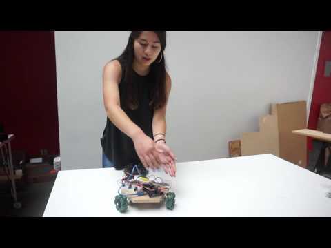
After reviewing the mechanical schematics of previous BlueStamp students who made omnidirectional robots, I decided that a hexagon would provide enough surface area for all my robot’s components. Next, I used easel.inventables.com to create an hexagon with 4 inch sides. Because I wanted a precise cut, I used a Computer Numerical Control Mill (CNC Mill) to cut out my base. A CNC Mill is a mill that is controlled by a computer. By connecting my computer to the CNC Mill, I sent the hexagon shape I desired to the mill via easel.inventables.com and the mill cut the shape out of plywood for me. Next, I mounted the motors to my base. I determined that mounting the motors in a Y shape would be the easiest way for my robot to move omnidirectionally because my wheels are evenly spaced. Since the motors are placed at an angle, the robot can easily move diagonally. However, the robot can also move forwards, backwards, and left and right because the motors can work together to counteract the angle they are placed at. I mounted my motors to the base using L brackets and wood screws. This entire process allowed me to gained comfortability with tools such as drills and screwdrivers. Finally, I coded the arrow buttons to move my robot forwards and backwards and the L2 and R2 buttons to the turn the robot left and right.
Final and Initial Designs for Chassis
Milestone 1

PS2 Receiver Electrical Schematic (from www.billporter.info)
My first accomplishment was connecting my PS2 controller to my Arduino Uno. I accomplished this by connecting a wireless receiver to its corresponding pins on the Arduino board. I then started practicing coding by coding my PS2 controller’s buttons to turn LEDs on and off. This taught be how to use if/else statements that would later help me code my motors. Next, I connected my three wheels to motors, connected the motors to motor controllers, and connected the motor controllers to my Arduino board. I connected the motors by following Chloe’s electrical schematic. Then, I used the PS2X_lib and the servo library, so I could code my motors to be controlled by my PS2 controller. I then coded my controller’s buttons to turn the wheels forward and backwards. The LEDs turned on when I pressed the circle or X button and the wheels spun forward when I pressed the R2 button and backwards when I pressed the L2 button. Because of this milestone, I gained experience with a breadboard because each component uses many cords. I learned that a breadboard has a negative and positive vertical column on its far right and left. Because I needed a ground pin for each motor and LED and I have a limited number of ground pins on my Arduino board, I connected a jumper wire from a ground pin on my Arduino board to a pin in one of the breadboard’s negative vertical columns. This column is vertically connected, meaning that every other pin in that column is now connected to ground. Likewise, each motor needed to be connected to the Arduino’s 5 volt pin because they are DC motors, meaning they require direct current. Since the Arduino has only one 5 volt pin, I connected a jumper wire from the 5 volt pin to one of the breadboard’s positive vertical columns. The biggest challenge I faced was coding in general. I had never coded before, so I had to do a lot of research to set up each motor and LED. Coding the motors was especially difficult because many websites coded them differently, but none of the code worked for my motors. I finally got my motors to work by using the writeMicroseconds() function, which allows my wheels to keep spin forwards and backwards continuously.
Starter Project
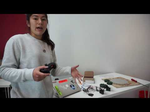
For my starter project, I made a Velleman voice changer. The voice changer is an electrical circuit that is made up of resistors, capacitors, integrated circuits, trimmers, a zener diode, a microphone, a battery, and a circuit board. I completed the circuit by soldering each part to the circuit board. The voice changer is powered by a 9V battery. It works by receiving sound waves through the microphone. The microphone turns the sound waves into an electrical signal which the IC can alter, causing the sound output to be at a different frequency. The different frequency of sound is what makes the output sound sound different to our ears. The resistors and the capacitors regulate how electrons flow through the circuit to keep the circuit from overheating. A diode allows electrons to flow in one direction only. A zener diode causes the electrons to flow in one direction as long as the voltage is below the zener voltage. If the voltage is higher than the zener voltage, the zener diode will force the electrons to flow in the reverse direction. This ensures that our circuit is constantly running at a voltage that it can handle. When I completed my project, it did not work at first. I was then challenged with finding any mistakes in my wiring that would cause my circuit to be incomplete. I discovered that behind behind my circuit board, the wires of some of my components were touching, which created connections that electrons could move through. This is called shorting and it disrupts the flow of electrons through the circuit. By uncrossing the wires and clipping them so that they could not touch, I ensured that the electrons would flow through the circuit in the correct direction. Another challenge I faced was understanding my circuit, because I was not familiar with most of the components. I had to do a lot of research to understand how each component assisted in altering a person’s voice. Through this project, I learned new vocabulary, how to solder, how a circuit works, and how to keep trying even when I am faced with challenges.
Holly,
This project is AMAZING, you should be so proud. Enjoy the rest of your summer. Thank you for all of your help with the shower , yesterday.
Take care,
Auntie