Hi, my name is George and I’m a rising senior at Archbishop Mitty High School. The Blue Stamp program has been a great learning experience. I enjoyed how we were given independence to choose our own projects and received minimal assistance. Because we weren’t given much assistance, I was forced to develop a research and troubleshooting strategy to make progress in my project. I was given the tools and motivation to complete my project and had to figure things out for myself. I especially enjoyed the talks the other students and I got from local entrepreneurs and engineers. However, one change that I would suggest is an in-person meeting to discuss one’s project (especially if it is an independent project) before the program starts.
Final Project: Starting with no previous knowledge of electronics or electromagnetism, I managed to design and build a Linear Motor

I chose to build a Linear Motor because I saw many applications for it. When I built this linear motor I envisioned its uses: The maglev train, a rail-gun, and even a personal use as an automated camera dolly. I knew it would be a challenge because I chose an independent project, meaning it was simply and idea; there were no instructions. I learned a how to use multiple components including resistors, transistors, relays, diodes, and Mosfets. I also gained valuable knowledge about electromagnetism and circuits.
The first step in building my linear motor was to determine the correct coil size and wire gauge, and finding an effective sequence to change the coils. As I learned, the fundamentals to a coil producing a magnetic field falls under the fact that any wire with current passing through it has a magnetic field – even if it is minuscule. When a wire is coiled, the magnetic field from the wire combines as the wires are wound on top of each other. I tested different wire gauges and sizes by seeing how far away the magnet could pick up a paperclip. I discovered that I could not use an iron core, which amplifies the magnetic field dramatically, because the magnets would be attracted to the core regardless of the pole I send to the coils. My results are posted below. When I found a desired wire gauge and size (16 AWG and 5/8” air core), I began to mass-produce the coils using a jig I created with a lathe. I found an affective coil sequence by drawing out the coils, placement of the cart at each step, and which magnets I would need to be pushing and pulling for the cart to move to the next step. The drawing of this process is attached below.
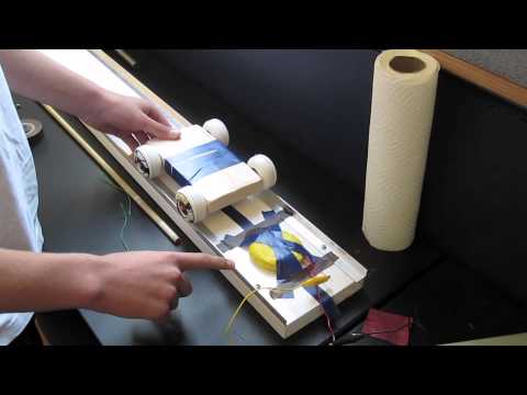
The next step was to create track and cart. The track was relatively simple to make. I used a 5.5” x 4’ plank with right angle aluminum extrusions on the sides. I made grooves in the wheels of the cart using my lathe to fit on these extrusions. I also had to make the cart as light as possible. I did this by using as little wood as possible. You can see my designs below.
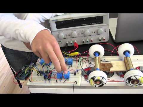
Finally, I had to figure out how to power my coils and be able to switch their poles. I did so by using a system of relays. With a certain arrangement of relays, I switched the poles by sending electricity through opposite sides of the coil. I had to power the relays with Mosfets because the Arduino did not have sufficient current to trigger the relays. The Arduino is what eventually controlled when the relays should switch and controlled the sequence of the coils. It is most simply understood by looking at my circuit below.
Some future improvements I plan on making include using an ultrasonic sensor to determine which coils should be triggered. I also plan to smoothen the motor by using transistors to make more of a Sine curve instead of an off/on system. I would use a system of transistors to do so. By doing this, I could control the exact placement of the cart on the track.
Code
_______________________________________________________________________________
July 11th 2013
My third milestone includes the jig that I have built to wind the coils. This jig uses a mini JET lathe to wind the coils, as well as a 5lb spool of 16 AWG copper wire. This coils take about 10 seconds to wind, but about 10 minutes to take off the mandrel and tape up.

_______________________________________________________________________________
July 3rd, 2013
My second milestone was building the track and cart. I did this by using a 5 1/2″ X 4′ wooden plank alone with 2 4′ right angle aluminum extrusions. For the cart, I used balsa wood to create a hollow chase. Then, I used 3/8″ dowels to attach 4 skateboard wheels.
_______________________________________________________________________________
July 2nd 2013
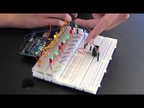
My first milestone in my main project is making the circuit to simulate the coils on the Linear motor. I used relays to give the LEDs (what will be the coils) extra power. I only had one relay by this time, so I could not simulate the entire 3 phase system.
_______________________________________________________________________________
June 7th, 2013
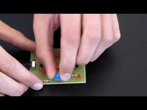
The starter project I selected and built was a laser target (Light sensor). The laser target illuminates 8 to 9 LED’s when the desired amount of light is present on the photoresistor. When the target is on night mode, the electricity first illuminates the 9th LED after it passes through a diode that limits the flow of electricity to be from only one direction. The purpose of this 9th LED (located next to the laser target sensor) is to demonstrate where the target is so that one can shine a laser on it in the night. Simultaneously and on a separate path, electric current passes through an initial resistor that limits the current that passes through to the rest of the circuit. After the current flows through the resistor, the electricity reaches a vertical trimmer resistor (or variable resistor) that simply is a resistor whose resistance can be changed based on the desired affect. Once the electricity passes through the vertical trimmer resistor, it reaches a Darlington pair of transistors. A Darlington pair of transistors is practically the same as a transistor except the pair of transistors work together to greaten the amplification of electricity. However, the current, when no light is shown on the device, is not great enough to switch the transistors and allow the current to flow through to the LEDs. This is because the photoresistor is applying an immense amount of resistance to the current. When light hits the photoresistor, the resistance it applies to the current is dramatically reduced and the result is a current great enough to switch the transistors and thus allow the flow of electricity through them. Once the transistors are switched and the current is flowing through the transistors, the differential between the two sides of each LED is great enough to illuminate it. When the target is on day mode, the electricity follows a similar path. The only difference, however, is that the 9th LED does not illuminate because the 9th LED has a diode which restricts the flow of electricity from the direction of the path of the day mode. My project was relatively straightforward the entire process. The only thing I had trouble with was learning what each component contributed to the entire circuit.
In order to operate the laser target, you first turn the switch to either day mode or night mode. Once it is in one of the modes, slowly adjust the variable resistor to where the LEDs are only just glowing. Then, turn it a fraction past that to where the LEDs are only just off. Once the laser target is in this arrangement, the LEDs will illuminate when one shines a light on it.