
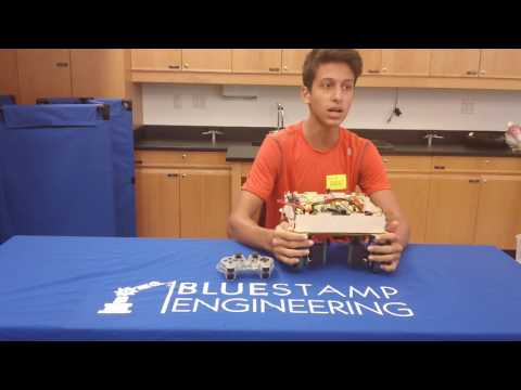
Hi, my name is Freddie. I am a rising junior at Trinity High School in New York City. I choose to participate in the BlueStamp engineering program because I enjoy learning and engineering. I built the MintyBoost phone charger for my starter project, and for my main project I constructed an RC swerve drive car. A swerve drive allows the car to go in any direction. However, instead of using special wheels used in typical omnidirectional RC cars like this, which do not allow for very quick movement/ varied drive systems, my design uses regular wheels and servos, creating opportunities for multiple different drive types and allowing the car to move faster. Because my RC car uses regular wheels that are more structurally sound and can go at higher speeds than omnidirectional wheels, it could, with more advanced supports than those I had time to build (and faster motors than those I used), be built as a full size car.
I chose the MintyBoost because it is useful and was very interesting to learn how it worked, and chose the RC swerve drive car because it seemed an interesting, challenging, and unique project with potential real world applications in the automobile industry.
Looking back at my time in BlueStamp, I have learned many things concerning my project, including growing my knowledge of electrical and mechanical engineering. I had a fun and interesting time with my peers making my project, and expect to branch out after BlueStamp, working on other projects I have planned, such as a drone and a complex robotic arm. BlueStamp has sparked my interest in many fields of engineering, fields that I plan on continuing to pursue and learn about in the future.
Here is a picture of my swerve drive RC car:

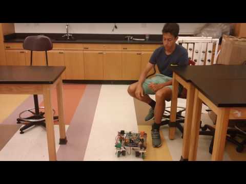
Final Video:
Final Milestone:
My final milestone was the completion of my swerve drive, the goal of my project. This involved the implementation of the servos and servo controller, as well as more complex code involving analog sticks. My controller includes 3 modes: a swerve drive mode, the tank drive mode of milestone 1, and a turn in place mode. Both the serve drive mode and turn in place mode have variable speed using the analog sticks. This milestone took up the remainder of my time at BlueStamp, as the mechanics of the chassis had to very fine-tuned in order to work, and my first chassis made my servos fail because of this. I then laser cut a chassis, which performed much better.
My final laser cut chassis is much more structurally sound, not only because the pieces are laser cut, but because the connector between the chassis and the wheel is much firmer and is made with nuts and bolts, instead of screws. In the first iteration of my chassis, I used screws, which resulted in slightly lopsided wheels due to the screws not going in all the way, and caused the servos to break.
A challenge I encountered while constructing the swerve drive was not only the mechanical design (which ultimately led to my servos failing, necessitating a remodeling), but also the coding for the analog sticks. This code was much more complicated than the tank drive code, as I needed to first figure out what “forward” was for each servo (each was positioned differently), but also had to come up with proper equations to transfer the position of the analog sticks into a pulse number between 1984 and 9600. This was achieved by looking at the value of the x axis of the right analog stick, and which quarter of the graph created by the right analog the value received from the stick was in.
Here is a picture of my final chassis:

The raised edges on this chassis are a result of a laser cutting mishap. Some lines, such as the slots these raised edges were supposed to fit in on the chassis, were not cut, and due to time restraints I could not recut the chassis.
Here are some pictures of my initial chassis (this was not structurally sound enough, and I had to take it apart and remodel it):


Here is the code for the Swerve drive: Swerve Drive Code
Here is my Student Defined Project Document, which includes my Bill of Materials and my Bill Plan.
Here are my .svg files, which were used to form my chassis (note: I did not use most of theses pieces, because many did not cut in time): Swerve Chassis Part 1 Swerve Chassis Part 2
These files use Inkscape, and can only be edited with Inkscape or a similar laser cutting applications.
Below is my Fritzing diagram:

Milestone 1:
My first milestone was a tank drive for my car. In order to achieve this, I had to connect the wireless PS2 receiver to the Arduino Mega, and get the h-bridges functioning in order to have the motors change speed and direction. Because the buttons on my Ps2 controller do not support pressure (can only be on or off), I was only able to have the wheels go at two speeds (full speed and no speed). When I make the swerve drive I will be able to have variable speed, because I will be using the analog joysticks.
A challenge I encountered was figuring out how my schematic should be assembled; this required me to learn in depth the functions of each part and pin in my circuit in order to set up the circuit for my purposes. For example, I had to understand how h bridges functioned ( not just what they did) in order to know where to apply power, what amount of power to apply, and which pins I should connect to.
Another challenge I found was interfacing the ps2 controller with the Arduino. Initially, when I got the ps2 to send signals to the Arduino,there was a delay in the response from the Arduino and sometimes the Arduino didn’t even register that it received a signal. In order to fix this, I debounced the code (making any button press under 10 milliseconds invalid), thinking that part of the reason it wasn’t responding or delaying in its response was because the buttons were pressing for milliseconds. After debouncing the code, it turned out that there was no response from the Arduino at all. After reviewing this, I realized the function from the ps2x library by Bill Porter that I used was the Button function, which was true for as long as the button was pressed. therefore, there was no timing to the button press, and no debouncing would work. Instead, I switched the debouncing to only allow the button to communicate if the button press was under 10 milliseconds. This, along with the attachment of some grounds I missed in my circuit, allowed my Arduino to communicate very quickly with my controller.
Here is my Code for the tank drive: Tank Drive Code
Below is my Fritzing diagram:

MintyBoost Starter Project:
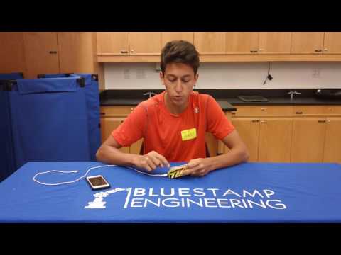
The basic setup of the minty boost is that current flows through an circuit of low resistance with an inductor. the low resistance causes a high current, generating a magnetic field in the inductor. The booster chip then turns a switch, opening the low resistance circuit and causing the current to flow through a higher resistance circuit where the load, or the charging phone, is. Because inductors resist changes in current, the inductor forces more current than would normally go through the load, using the energy stored in the magnetic field and increasing the voltage. The booster chip does this very often very quickly because the magnetic field reaches maximum strength very quickly. Once the voltage reaches 5V, the sense pin in the booster chip recognizes this and stops the quick switching so that current just flows through the load. This continues until the voltage drops below 5V (because the load is taking energy), and at this point the rapid switching that was used to increase the voltage resumes.
Hi Freds, I am really happy for you. I love the moving car as well as the phone charger. I am impressed with how much you had to tinker to get is all to work specially the car, and then hearing you fully present the technical challenges and what each piece does, and how all work together to give it such neat controlled motion, very cool. Really impressive.
Freddie,
this is an amazing project. I am so impressed how you came up with the design and put it into physicality, digging deep into mechanical and electrical engineering.
Congratulations for an outcome that shows your dedication, focus and persistence.
Wishing you great success and fun with all your other projects in the pipeline, Nicola