Robotic Hand
Hello, my name is Fatima and I am a rising junior at Newark Collegiate Academy. My main project at this STEM summer camp for kids is a 3d printed hand controlled by a separate glove with flex sensors and an Arduino. The flex sensors control the Arduino which controls the servos which controls the hand.
Engineer
Fatima A
Area of Interest
Computer Engineering
School
Newark Colligiate Academy
Grade
Incoming Junior
Reflection
My experience at Bluestamp proved to be very difficult yet rewarding. I learned many engineering skills such as soldering and troubleshooting. BlueStamp also changed the way I think. I used to assume that if there was something wrong it would be an extremely complicated issue, but then I started to realize that some issues have really simple solutions. For example, I realized that my project was not turning on because it was not plugged in, not that it was completely broken. From my time here, I also learned my strengths and weaknesses in engineering. I thought I would enjoy programming and getting code to work, but I learned I am terrible at programming. I thought I would not like working with my hands and mechanical engineering, but working on this project showed me that with the right pieces it can be very satisfying to see a project come together. I got better at wiring and realized that it is something I like. I had no prior experience with any forms of engineering and I had a lot of difficulty with this project, but it taught me a lot about myself and engineering. After this summer and this project, I realize I would like to go into electrical engineering.
Final Milestone
Figure 1
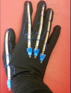
For my third milestone, I completed the base project: a 3D printed hand controlled by a separate glove. In the finished project, when a user bends a finger on the glove the corresponding finger on the hand will bend in real time. For example, if the user bends their index finger the hand will also bend the index finger. First, I sewed the flex sensors onto the fingers of the glove as seen in the image above. In my project, the ring finger and the pinky share a servo, so only one of them needs to have the flex sensors attached. I used the same Arduino and breadboard from milestone 1 and kept the servos and flex sensors attached to the breadboard through the use of jumper cables. The Arduino has the same code as it did in milestone 1, which I got from dschurman on this instructables page While working on this milestone, I had a lot of mechanical issues. One example is when I shorted out an Arduino by plugging in the battery wrong. One non-mechanical issue that I had was that when the fingers on the glove were straight the fingers in the hand would bend, and when the fingers on the glove would bend the fingers on the hand would straighten themselves. I fixed this by changing the map function of the servos so they would turn from 180 to 0 instead of 0 to 180. I changed the code from:
pos1 = constrain(pos1, 0, 180); int pos2 = map(flex2, 400, 700, 0, 180);
to
pos1 = constrain(pos1, 0, 180); int pos2 = map(flex2, 400, 700, 180, 0); In Arduino, the map function takes in an input and scales it through the input range then the output range and then gives out an output. For example, in this project the input is the flex sensor value and the input range is based on resistance of the flex sensor. The actual input is the ADC value of the flex sensor. ADC stands for analog digital conversion and is used to convert the analog voltage in the pins to a digital number. This is useful because it can change the analog signal into a digital one without changing the value. ADC is used in this project by changing the flex data in the analog pins from an analog value to a digital value that the servos can understand. The amount of flex sensor voltage is put through the input range and scaled to the output range which is what position the servos will turn to. Learn more about ADC and Arduino analog pins here. The servos are the output of the function and after the flex sensor bends the servos will move to a position between 0 and 180. The flex sensors were mapped into a range between 400 and 700 because those are the values where the fingers were fully open or closed. Although I had a lot of issues with getting this project to work, one thing that I enjoyed while doing this milestone was finally getting everything to work properly after days of trying.
pos1 = constrain(pos1, 0, 180); int pos2 = map(flex2, 400, 700, 0, 180); pos1 = constrain(pos1, 0, 180); int pos2 = map(flex2, 400, 700, 180, 0); In Arduino, the map function takes in an input and scales it through the input range then the output range and then gives out an output. For example, in this project the input is the flex sensor value and the input range is based on resistance of the flex sensor. The actual input is the ADC value of the flex sensor. ADC stands for analog digital conversion and is used to convert the analog voltage in the pins to a digital number. This is useful because it can change the analog signal into a digital one without changing the value. ADC is used in this project by changing the flex data in the analog pins from an analog value to a digital value that the servos can understand. The amount of flex sensor voltage is put through the input range and scaled to the output range which is what position the servos will turn to. Learn more about ADC and Arduino analog pins here. The servos are the output of the function and after the flex sensor bends the servos will move to a position between 0 and 180. The flex sensors were mapped into a range between 400 and 700 because those are the values where the fingers were fully open or closed. Although I had a lot of issues with getting this project to work, one thing that I enjoyed while doing this milestone was finally getting everything to work properly after days of trying.
Second Milestone
Figure 1
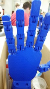
Figure 2
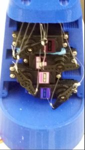
For my second milestone, I constructed the hand and connected the string and servos to the hand. As I said in my first milestone, servos are small motors where you command exactly how far to rotate. The servos are attached to strings that go through each of the fingers. This milestone was completely mechanical, so as of right now I do not have any power going to the servos, so they cannot pull the fingers. I had a lot of challanges with this part because the strings need to be in the perfect position where they are not being pulled too much or too little otherwise it will not pull the fingers. To get to this point I had a lot of issues with putting every part together. First, I screwed together the fingers and had a lot of difficulty getting the screw to fit into the holes. To get the screw in I had to drill and file the holes to the right sizes. I later realized that I used the wrong screws which made the fingers too stiff. After I had the whole hand together, I started to put the string through each finger. Since the hand was 3D printed there were a lot of small pieces of plastic in the string holes that I had to drill to get the string through. Once I had string going through each of the fingers and all the right screws, I saw that the string was too thick for it to bend the fingers. I then changed the strings, but they were too thin and were not able to pull the fingers. I changed the string one more time and then it was (finally!) the right size. The strings would slip through the fingers so I used hot glue on the tips of the finger to stop them. In figure 1 you can see the correct strings going through the fingers and some of the glue on top to hold them down. Next I attached the string to the servo heads and pulled them to see if they could pull the fingers down. First I tried looping the string through the servos but they would just slip through. Next I tried to tie them, but my knots kept coming loose. Then I tried to keep the string on the servos with hot glue, but the strings would pull off the glue. Finally, I used crimp tubes to hold the strings securely. In figure 2 you can see the servos attached to the arm and the strings attached to the servos heads with crimp tubing. Now the fingers were able to move, but there was still a lot of friction between the different parts of the fingers. To make the movements more fluid I filed down parts of the fingers. Now the servos can pull the strings and the fingers well.One thing that I learned from this milestone is to test pieces of a larger project one at a time and check for issues instead of doing everything at once and finding out it does not work. The idea of doing one thing at a time would have been useful when I was testing out the screws, strings, and how well the strings are connected to the servos.
First Milestone
#include //Includes servo library

//Define sensors and servos

Servo finger1, finger2, finger3, finger4, finger5;

int servoPin1 = 5;

int servoPin2 = 6;

int servoPin3 = 9;

int servoPin4 = 10;

int servoPin5 = 3;
int flexPin1 = A0;
int flexPin2 = A1;
int flexPin3 = A2;
int flexPin4 = A3;
int flexPin5 = A4;
void setup()
{
//Attach the servo objects to their respective pins
finger1.attach(servoPin1);
finger2.attach(servoPin2);
finger3.attach(servoPin3);
finger4.attach(servoPin4);
finger5.attach(servoPin5);
Serial.begin(9600);
/* set each servo pin to output; I’m not acutally sure if this is
even necessary, but I did just in case it is */
pinMode(servoPin1, OUTPUT);
pinMode(servoPin2, OUTPUT);
pinMode(servoPin3, OUTPUT);
pinMode(servoPin4, OUTPUT);
pinMode(servoPin5, OUTPUT);
//Set each flex sensor pin to input: this is necessary
pinMode(flexPin1, INPUT);
pinMode(flexPin2, INPUT);
pinMode(flexPin3, INPUT);
pinMode(flexPin4, INPUT);
pinMode(flexPin5, INPUT);
}
void loop()
{
//Defines analog input variables
int flex1 = analogRead(flexPin1);
int flex2 = analogRead(flexPin2);
int flex3 = analogRead(flexPin3);
int flex4 = analogRead(flexPin4);
int flex5 = analogRead(flexPin5);
/* Defines “pos” variables as being proportional to the flex inputs.
The 400 to 700 value range seemed adequate for my sensors, but you can change
yours accordingly. */
Serial.print(“flex sensor 1: “);
Serial.println(flex1);
Serial.print(“flex sensor 2: “);
Serial.println(flex2);
Serial.print(“flex sensor 3: “);
Serial.println(flex3);
Serial.print(“flex sensor 4: “);
Serial.println(flex4);
//delay(1000);
int pos1 = map(flex1, 400, 700, 0, 180);
pos1 = constrain(pos1, 0, 180);
int pos2 = map(flex2, 400, 700, 0, 180);
pos2 = constrain(pos2, 0, 180);
int pos3 = map(flex3, 400, 700, 0, 180);
pos3 = constrain(pos3, 0, 180);
int pos4 = map(flex4, 480, 640, 0, 180);
pos4 = constrain(pos4, 0, 180);
int pos5 = map(flex5, 400, 700, 0, 180);
pos5 = constrain(pos5, 0, 180);
//Tells servos to move by the amount specified in the “pos” variables
finger1.write(pos1);
finger2.write(pos2);
finger3.write(pos3);
finger4.write(pos4);
finger5.write(pos5);
}
#include //Includes servo library
//Define sensors and servos
Servo finger1, finger2, finger3, finger4, finger5;
int servoPin1 = 5;
int servoPin2 = 6;
int servoPin3 = 9;
int servoPin4 = 10;
int servoPin5 = 3;int flexPin2 = A1;
int flexPin3 = A2;
int flexPin4 = A3;
int flexPin5 = A4;
{
//Attach the servo objects to their respective pins
finger1.attach(servoPin1);
finger2.attach(servoPin2);
finger3.attach(servoPin3);
finger4.attach(servoPin4);
finger5.attach(servoPin5);
Serial.begin(9600);
/* set each servo pin to output; I’m not acutally sure if this is
even necessary, but I did just in case it is */
pinMode(servoPin1, OUTPUT);
pinMode(servoPin2, OUTPUT);
pinMode(servoPin3, OUTPUT);
pinMode(servoPin4, OUTPUT);
pinMode(servoPin5, OUTPUT);
pinMode(flexPin1, INPUT);
pinMode(flexPin2, INPUT);
pinMode(flexPin3, INPUT);
pinMode(flexPin4, INPUT);
pinMode(flexPin5, INPUT);
{
//Defines analog input variables
int flex1 = analogRead(flexPin1);
int flex2 = analogRead(flexPin2);
int flex3 = analogRead(flexPin3);
int flex4 = analogRead(flexPin4);
int flex5 = analogRead(flexPin5);
The 400 to 700 value range seemed adequate for my sensors, but you can change
yours accordingly. */
Serial.print(“flex sensor 1: “);
Serial.println(flex1);
Serial.print(“flex sensor 2: “);
Serial.println(flex2);
Serial.print(“flex sensor 3: “);
Serial.println(flex3);
Serial.print(“flex sensor 4: “);
Serial.println(flex4);
//delay(1000);
pos1 = constrain(pos1, 0, 180);
int pos2 = map(flex2, 400, 700, 0, 180);
pos2 = constrain(pos2, 0, 180);
int pos3 = map(flex3, 400, 700, 0, 180);
pos3 = constrain(pos3, 0, 180);
int pos4 = map(flex4, 480, 640, 0, 180);
pos4 = constrain(pos4, 0, 180);
int pos5 = map(flex5, 400, 700, 0, 180);
pos5 = constrain(pos5, 0, 180);
finger1.write(pos1);
finger2.write(pos2);
finger3.write(pos3);
finger4.write(pos4);
finger5.write(pos5);
}
For my project at Bluestamp, a STEM summer program in New York, I am making a robotic hand that is controlled by a separate glove. My first milestone during this project is getting the flex sensors, Arduino, and servos to work in sync. Flex sensors are variable resistors. Like constant resistors, variable resistors create a change in the flow of the current but the value of resistance changes when the variable aspect of the resistor is influenced by an outside force. For example, flex sensors have more resistance the more the body of the sensor bends and less resistance the less it bends. The flex sensors are a part of a voltage divider which is a simple circuit that reduces a large voltage to a smaller one through the use of resistors. Arduinos are a type of programmable microcontrollers used to segment code into functions to carry out a task. Servos are small motor like objects with rotating heads. The main difference between servos and motors are that once a motor is powered it will turn until it runs out of power, but a powered servo can be controlled by pulses of energy that control the rotation of the top.
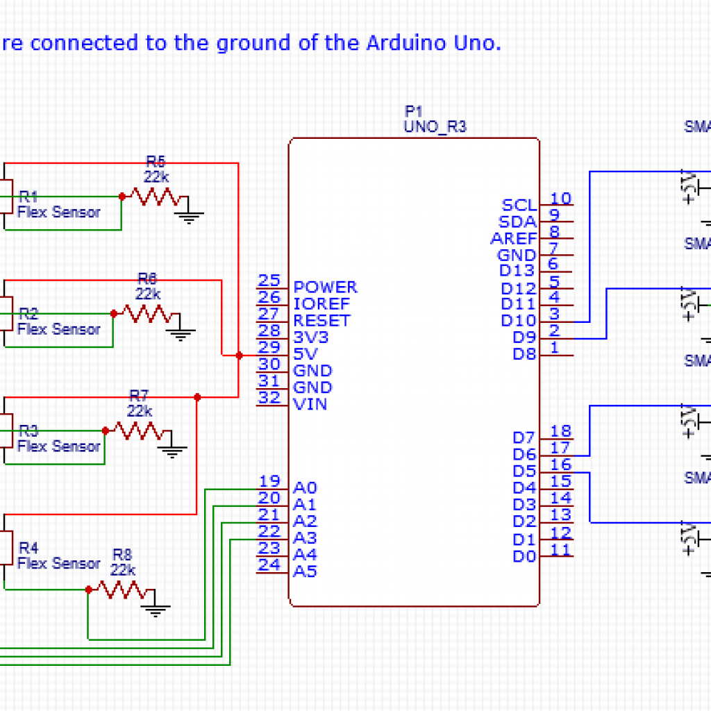
The schematic above shows the connections between the Arduino, flex sensors, and servos. The flex sensors are used along with constant resistors so the Arduino can monitor the bend in the resistors. The flex data is then relayed to the servos and the servos rotate if necessary. All of the components are connected through a breadboard, a board used for experimental circuits, and attached as shown above. I attached the ground and 5v of the Arduino Uno to the breadboard then I added in the flex sensors and resistors. The servos were plugged into the Arduino and not the breadboard so that the Arduino could send out a current to the flex sensors, retrieve the flex data, and relay the information to the servos.
The code I used was written by the user dschurman on this instructables page, and it gives the Arduino the ability to connect the flex sensors and servos. As previously mentioned, the Arduino, flex sensors, and servos are all connected, but they can only work because of the code that was put onto the Arduino. For example, the sections of code that start with “pinMode(flexPin1, INPUT);” and “pinMode(servoPin1, OUTPUT);” connect the flex sensors and servos as inputs and outputs for giving and receiving data to or from the computer, or in this case Arduino. This is repeated for each of the four flex sensors and servos.
This is a milestone for me because to get to this point I learned how to use an Arduino, understand the purpose of different lines of code, how to adjust a code to make it more understandable and efficient, and how to use a breadboard.While figuring out how to make the Arduino work with the flex sensors, one issue I had was getting the serial monitor to display the flex data properly. I fixed this by altering the code so that the Arduino would stop trying to change the variable “flex sensor 1” and start changing the data given to it from the flex sensor.
the useless machine