Phone-Controlled Robot Arm
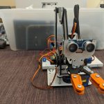
Technology has vastly improved within recent years, with an important creation being the Robotic Arm; an efficient way to perform menial tasks. The Robotic Arm can move and pick-up objects and is wireless thanks to a Bluetooth Wireless Communication Module.
Engineer
Ethan S
Area of Interest
Computer Engineering
School
Los Altos High School
Grade
Incoming Sophmore
Final Reflection
Ultrasonic Sensor
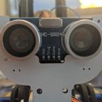
An ultrasonic sensor is a sensor that can measure distance by emitting ultrasonic waves, which are incredibly high-frequency waves that the human ear cannot pick-up on. The sensor is able to measure distance by measuring the time between the emission and reception. An ultrasonic sensor has four pins, VCC(power), GND(ground), ECHO(Receive), and TRIG(transmit). Light, smoke, dust, color, and materials do not affect the ultrasonic sensor in any way. Ultrasonic sensors are widely used due to their versatility and resilience.
What I Plan to Do
The modification I decided to use for my robotic arm was to attach an ultrasonic sensor. By using the ultrasonic sensor, I will be able to tell how far away objects are from my robotic arm. I could use this to have my robotic arm try to sense nearby objects and pick them up. So far, I have been able to properly wire my ultrasonic sensor to my Arduino and have written properly functioning code but have not been able to fully incorporate it into my app on my phone. Also, my code is not perfect: it is messy and could be written neater. I hope sometime in the near future I will be able to complete this modification and have a robotic arm that can sense the distance it is from another object besides already being wireless. Another modification I hope to do in the future is to attach a camera to my robotic arm. If I succeed then it will work well with the ultrasonic sensor: I will be able to see objects and tell how far away they are. Finally, there has been one slightly annoying problem I have with my robotic arm. Whenever I try to move the slider up and down, there is a decent chance that my robotic arm will jitter(this does not happen if I tap different values on the slider, only if I press and move the slider). From much testing I have found out that the cause of this problem is servo fluttering. Unfortunately the only solution I could find to fix this problem would be to use ferrite cores which I sadly do not have on hand. I plan on hopefully ordering four ferrite cores(one for each servo) from Amazon at a later date.
Reflection
During my time at Bluestamp, I have learned a great deal about myself and what I love about engineering. I have realized I enjoy hands-on work such as wiring or building compared to the software side of engineering like coding. I have also realized that I need to practice coding more; compared to all the other aspects of engineering, I faced the most trouble when trying to code for my project. Overall, Bluestamp was a great experience. In the short amount of time that I was there I have learned a great deal and built a functioning wireless robotic arm from scratch!
Second Milestone
Designer Interface

Block Editor
MIT App Inventor
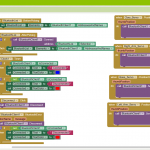
The MIT App Inventor is an easy place that allows users to build simple apps and connect them to their phone. The MIT App Inventor has two separate parts to it, the designer interface and the block editor of the app. The designer interface is where the app interface is designed while the block editor program’s the app’s behavior by putting blocks together. The designer interface has three components: the Palette which has all the different components that can be added to the app, the properties for each component, and the Viewer which allows you to see what the app will look like. The block editor also has three major components: the Built-In Drawers which has blocks for general behaviors, the Component-Specific Drawers which has blocks for specific behaviors, and the Viewer which allows blocks to be adjoined building relationships and behaviors.
For my app, I created a simple design. In the design, there are four different sliders each controlling a different servo on my robot. I used a Block Editor such that when each slider is moved it sends a signal to the Arduino such as S1 or S2 depending on the servo and the position the servo should move to. At the top of the app, I created a connect and disconnect button such that the app could be linked to my Bluetooth module. When creating the connect button, I had the app search for nearby Bluetooth Modules it could connect to. Combined together, the app that I created is a simplistic app that is easy to use and can control all four servos on the robotic arm.
Bluetooth Module
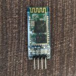
A Bluetooth Module is a wireless communication protocol; it sends and receives data over a limited range. The module consists of four main parts: the radio, the Link Controller, the Link Manager, and the Application Software. Although Bluetooth Modules can vary, all modules have 4 different pins, the vcc(power), the GND(ground), the TX(transmit), and the RX(receive).
Challenges
I had one main challenge during the second milestone. Whenever I moved the slider on the app, my robot arm would jitter and go out of control. I had great difficulty finding a solution to the problem. First I decided to rewired the Bluetooth Module before trying again but nothing changed. I then used the serial.print function to see what commands were being given. By using the function I found out that the code was not creating a new line each time it noticed a new command but instead formed one long line of gibberish. Chris, one of the instructors, decided to help me by writing new code for the robotic arm because there were multiple errors in the original code. This kind of solved the problem; the commands work fine yet the robotic arm still jitters uncontrollably if I move the sliders. I hope to fix this problem for my third milestone.
How I Built It
For Milestone 2, most of the work was focused on software instead of hardware. First, I created an app on the MIT App Inventor and used the Block Editor to add specific behaviors. I then wired my Bluetooth module to the Arduino which was somewhat of a challenge. Afterward, I completely changed my code so it would be compatible with my app. At this stage I thought I was done, however when using the app, the servos on my Robot Arm went haywire. To solve this I first re-wired my Bluetooth Module, attaching both to the breadboard and Arduino yet that did not fix the problem. Then, with the help of an instructor, I yet again completely changed the code I had been using, for there were multiple errors in the previous one. I then tested it out and was ecstatic to find that my robotic arm properly functioned.
/*
DIY Arduino Robot Arm Smartphone Control
by Dejan, www.HowToMechatronics.com
Updated by Christopher, www.github.com/gamma2653
*/
#include <SoftwareSerial.h>
#include <Servo.h>
Servo servo01;
Servo servo02;
Servo servo03;
Servo servo04;
Servo servo05;
Servo servo06;
SoftwareSerial Bluetooth(3, 4); // Arduino(RX, TX) – HC-05 Bluetooth (TX, RX)
int servo1Pos, servo2Pos, servo3Pos, servo4Pos, servo5Pos, servo6Pos; // current position
int servo1PPos, servo2PPos, servo3PPos, servo4PPos, servo5PPos, servo6PPos; // previous position
int servo01SP[50], servo02SP[50], servo03SP[50], servo04SP[50], servo05SP[50], servo06SP[50]; // for storing positions/steps
int speedDelay = 20;
int index = 0;
String dataIn = “”;
const String END_OF_MSG = “;”;
void setup() {
servo01.attach(9);
servo02.attach(10);
servo03.attach(5);
servo04.attach(6);
servo05.attach(7);
servo06.attach(11);
Serial.begin(9600);
Bluetooth.begin(9600); // Default baud rate of the Bluetooth module
Bluetooth.setTimeout(1);
delay(20);
// Robot arm initial position
servo1PPos = 20;
servo01.write(servo1PPos);
servo2PPos = 90;
servo02.write(servo2PPos);
servo3PPos = 140;
servo03.write(servo3PPos);
servo4PPos = 40;
servo04.write(servo4PPos);
servo5PPos = 85;
servo05.write(servo5PPos);
servo6PPos = 80;
servo06.write(servo6PPos);
}
void moveServo(Servo servo, int& ppos, int pos, int delayTime) {
if (ppos > pos) {
// We use for loops so we can control the speed of the servo
// If previous position is bigger then current position
for ( int j = ppos; j >= pos; j–) { // Run servo down
servo.write(j);
delay(delayTime); // defines the speed at which the servo rotates
}
}
// If previous position is smaller then current position
if (ppos < pos) {
for ( int j = ppos; j <= pos; j++) { // Run servo up
servo.write(j);
delay(delayTime);
}
}
ppos = pos; // set current position as previous position
}
void loop() {
// Check for incoming data
if (Bluetooth.available() > 0) {
dataIn = dataIn + Bluetooth.readString(); // Read the data as string
}
// Handle servo motor sliders
int indexOfEnd = dataIn.indexOf(END_OF_MSG);
while (indexOfEnd != -1) {
// Serial.print(“Data had end of line character: “);
// Serial.println(dataIn);
String servoType = dataIn.substring(0, 2);
String datum = dataIn.substring(2, indexOfEnd);
// Serial.print(“Possible servo datum: “);
// Serial.println(datum);
if (dataIn.startsWith(“S1”)) {
// Move Servo 1
servo1Pos = datum.toInt(); // Convert the string into integer
Serial.print(“Moving servo 1 to: “);
Serial.println(servo1Pos);
moveServo(servo01, servo1PPos, servo1Pos, 20);
// Remove command from buffer
dataIn = dataIn.substring(indexOfEnd + 1, dataIn.length());
} else if (dataIn.startsWith(“S2”)) {
// Move Servo 2
servo2Pos = datum.toInt();
// Serial.print(“Moving servo 2 to: “);
// Serial.println(servo2Pos);
moveServo(servo02, servo2PPos, servo2Pos, 20);
dataIn = dataIn.substring(indexOfEnd + 1, dataIn.length());
} else if (dataIn.startsWith(“S3”)) {
// Move Servo 3
servo3Pos = datum.toInt();
// Serial.print(“Moving servo 3 to: “);
// Serial.println(servo3Pos);
moveServo(servo03, servo3PPos, servo3Pos, 20);
dataIn = dataIn.substring(indexOfEnd + 1, dataIn.length());
} else if (dataIn.startsWith(“S4”)) {
// Move Servo 4
servo4Pos = datum.toInt();
// Serial.print(“Moving servo 4 to: “);
// Serial.println(servo4Pos);
moveServo(servo04, servo4PPos, servo4Pos, 20);
dataIn = dataIn.substring(indexOfEnd + 1, dataIn.length());
} else if (dataIn.startsWith(“s5”)) {
// Move Servo 5
servo5Pos = datum.toInt();
// Serial.print(“Moving servo 5 to: “);
// Serial.println(servo5Pos);
moveServo(servo05, servo5PPos, servo5Pos, 20);
dataIn = dataIn.substring(indexOfEnd + 1, dataIn.length());
} else if (dataIn.startsWith(“s6”)) {
// Move Servo 6
servo6Pos = datum.toInt();
// Serial.print(“Moving servo 6 to: “);
// Serial.println(servo6Pos);
moveServo(servo06, servo6PPos, servo6Pos, 20);
dataIn = dataIn.substring(indexOfEnd + 1, dataIn.length());
} else if (dataIn.startsWith(“SAVE;”)) {
servo01SP[index] = servo1PPos; // save position into the array
servo02SP[index] = servo2PPos;
servo03SP[index] = servo3PPos;
servo04SP[index] = servo4PPos;
servo05SP[index] = servo5PPos;
servo06SP[index] = servo6PPos;
index++; // Increase the array index
dataIn = dataIn.substring(5, dataIn.length());
} else if (dataIn.startsWith(“RUN;”)) {
runservo(); // Automatic mode – run the saved steps
dataIn = dataIn.substring(4, dataIn.length());
} else if (dataIn.startsWith(“RESET;”)) {
memset(servo01SP, 0, sizeof(servo01SP)); // Clear the array data to 0
memset(servo02SP, 0, sizeof(servo02SP));
memset(servo03SP, 0, sizeof(servo03SP));
memset(servo04SP, 0, sizeof(servo04SP));
memset(servo05SP, 0, sizeof(servo05SP));
memset(servo06SP, 0, sizeof(servo06SP));
index = 0; // Index to 0
dataIn = dataIn.substring(6, dataIn.length());
} else {
break;
}
indexOfEnd = dataIn.indexOf(END_OF_MSG);
}
}
// Automatic mode custom function – run the saved steps
void runservo() {
while (dataIn != “RESET”) { // Run the steps over and over again until “RESET” button is pressed
for (int i = 0; i <= index – 2; i++) { // Run through all steps(index)
if (Bluetooth.available() > 0) { // Check for incomding data
dataIn = Bluetooth.readString();
if ( dataIn == “PAUSE”) { // If button “PAUSE” is pressed
while (dataIn != “RUN”) { // Wait until “RUN” is pressed again
if (Bluetooth.available() > 0) {
dataIn = Bluetooth.readString();
if ( dataIn == “RESET”) {
break;
}
}
}
}
// If speed slider is changed
if (dataIn.startsWith(“ss”)) {
String dataInS = dataIn.substring(2, dataIn.length());
speedDelay = dataInS.toInt(); // Change servo speed (delay time)
}
}
// Servo 1
moveServo(servo01, servo01SP[i], servo01SP[i + 1], speedDelay);
// Servo 2
moveServo(servo02, servo02SP[i], servo02SP[i + 1], speedDelay);
// Servo 3
moveServo(servo03, servo03SP[i], servo03SP[i + 1], speedDelay);
// Servo 4
moveServo(servo04, servo04SP[i], servo04SP[i + 1], speedDelay);
// Servo 5
moveServo(servo05, servo05SP[i], servo05SP[i + 1], speedDelay);
// Servo 6
moveServo(servo06, servo06SP[i], servo06SP[i + 1], speedDelay);
}
}
}
First Milestone
Components
The three most important mechanical components in the Robotic Arm are the Arduino, servo, and potentiometer.
Servo
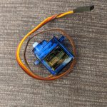
A servo is a motor that can be controlled and has three separate wires: ground(dark brown wire), power(red wire), and signal(orange wire). However, servos can only rotate 180 degrees and require significant power. In the robotic arm there are four different servos, one servo controls the base, two servos control the arm, and one servo controls the claw. Each servo is wired to the potentiometer and the Arduino.
Potentiometer
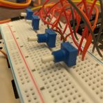
A potentiometer is a three-pronged dial that divides and adjusts the voltage. This basically means that a potentiometer is a three-pronged variable resistor. I used a potentiometer for each servo in the robotic arm. I can adjust the voltage thus causing the servo to move by turning the dial on the servo. Using a potentiometer allows me to easily see if the servo works or if there is a problem in the code or wiring.
Arduino
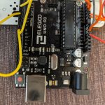
The Arduino is a vital component of the Robotic Arm and features in all sorts of electronic projects as the “brains”. The Arduino has a power indicator, an integrated circuit, a voltage regulator, and multiple different types of pins to construct a circuit. For my robotic arm, I used the Arduino both as a physical circuit board and a piece of software to upload my code.
Wiring
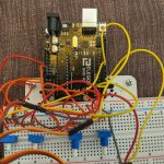
Frontal View
Challenges
The main challenge I faced happened when I was trying to get the second servo to work(move). When turning the potentiometer the servo refused to move. I re-wired and re-coded for the second servo thinking that I had accidentally made a mistake somewhere yet the servo continued to remain frozen. After pondering about the problem for a decent amount of time I realized that I may have limited free travel by tightening the arm two much which would cause the servos to be unable to move. I then loosened the screws and tested the servo which then moved. Also, I faced a minor problem. It was difficult getting the wires into the breadboard and many of my wires broke. My solution was to use a plier to insert the wire into the breadboard.
How I Built It
To start my project I first created a Bill of Materials to make sure that I had acquired all the parts. Then decided to build the robotic arm and attach the servos. Afterward, I wired a servo to the breadboard and Arduino before writing the code. Finally, I used a potentiometer to test whether the servo worked before moving onto the next servo. After wiring all four servos and writing code I tested all four servos and was ecstatic that they all worked properly.
My first milestone helped me learn a decent amount about the Arduino and wiring. Before I had never used an Arduino but I now have a strong understanding of what and how to use an Arduino. Wiring the servos and using potentiometers was a new experience for me.
#include <Servo.h>
Servo myservo; // right servo
Servo myservo2; // bottom servo
Servo myservo3; // claw servo
Servo myservo4; // left servo
int potpin = 0; // analog pin used to connect the potentiometer
int potpin2 = 1;
int potpin3 = 2;
int potpin4 = 3;
int val; // variable to read the value from the analog pin
int val2;
int val3;
int val4;
void setup() {
myservo.attach(9); // attaches the servo on pin 9 to the servo object
myservo2.attach(10);
myservo3.attach(3);
myservo4.attach(5);
}
void loop() {
val = analogRead(potpin); // reads the value of the potentiometer (value between 0 and 1023)
val = map(val, 0, 1023, 0, 180); // scale it to use it with the servo (value between 0 and 180 – degrees the servo can turn)
myservo.write(val); // sets the servo position according to the scaled value
delay(15); // waits for the servo to get there; 15 delay = .015 seconds
val2 = analogRead(potpin2);
val2 = map(val2, 0, 1023, 0, 180);
myservo2.write(val2);
delay(15);
val3 = analogRead(potpin3);
val3 = map(val3, 0, 1023, 0, 180);
myservo3.write(val3);
delay(15);
val4 = analogRead(potpin4);
val4 = map(val4, 0, 1023, 0, 180);
myservo4.write(val4);
delay(15);
}