
Ethan H’s BlueStamp Page
Hi, my name is Ethan, and I am currently a rising sophomore at the Dalton school. This is my first time at BlueStamp and it is also my first experience dealing with and learning about electrical engineering. For a long time I have been interested in making my own projects, like manufacturing my own stick-shift go-kart from scratch, but I have always lacked the ability to act on my interests. With the help of BlueStamp, my goal is to learn as much as I can in order to create a stable foundation with which I can use to make my own projects in the future, absent of BlueStamp. For my starter project I chose to work on the “BigTime Watch” and learn a little about microcontrollers and LED displays. The watch required me to learn a little about bits and bytes which was very interesting. Afterwards, for my main project, I decided to work on a laser-based security system. The idea behind this security system is that if you break a laser beam, then the alarm will go off. I was not only able to finish the security system, but I was also able to implement a couple of modifications such as: a card scanner, and wireless transceivers.
Reflection:
I’ve personally had a great experience, so much that I actually came back for an extra week. Although I initially thought that there would not be very much of a social environment, that actually ended up being one of my favorite parts of BlueStamp. I have learned many things at BlueStamp, but the most valuable lesson would be self-sufficiency, relying on yourself…and google for the solution. I am very glad that I came to this program because for a long time I’ve always been interested in many different disciplines of engineering but have lacked the skills and knowledge to pursue any of my interests. Therefore, with BlueStamps training, now I think I will actually be able to continue with this field and make projects I’ve always wanted to make.
Documentation:
- Bill of Materials
- Build Plan
- Code:
- Schematics:
- Schematic for final milestone – photoresistor – PDF – Fritzing File
- Schematic for final milestone – laser – PDF – Fritzing File
- Schematic for second milestone – PDF-- Fritzing File
- Schematic for first milestone – PDF – Fritzing File
Final Project:
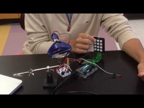
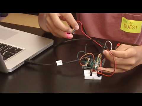
For my final project I was able to implement a couple of modifications. First, I was able to interface an RFID card scanner into my security system, and second, I was able to split up my project into two parts and have them communication wirelessly. For the ID card scanner, I used a kit, but for the wireless modules, I got the parts and had to interface it myself which was substantially harder than the ID card scanner. The idea of splitting my project up into two parts is not so much for functionality, but I did it mainly because I  wanted to experiment with and learn about wireless communication. The two parts are made up of an Arduino with a photoresistor which reads the amount of light which is hitting it – thereby telling us if the laser is connected or not – and the other part is made up of the security aspects – the keypad and ID card scanner. Initially, I struggled with actually getting the wireless transceivers to work because I started off by following a tutorial which told be to solder on a capacitor for energy purposes, but then I figured out that the capacitor is what was actually inhibiting the transceivers from actually working. Afterwards, it was the wireless communication library that was tough for me as well. However, after buckling down and just doing the work, I was able to push through and persevere. I think that the best part about doing this project was simply just the hands-on experience and having to understand concepts by myself.
The system works mainly with the help of the Arduino and the wireless modules. The Arduino with all of the security implementations on it, turns on a laser which is then directed and pointed at the photoresistor on the other Arduino. This Arduino then reads how much light is hitting it, determining whether the laser has been broken or not(when the laser is in contact with the photoresistor, the amount of light the Arduino reads is significantly more than when the photoresistor is just in contact with normal  amounts of light. The Arduino with the photoresistor then determines whether the laser has been broken or not, and sends the laser’s state to the other Arduino. The wireless transceivers work by using radio waves and electromagnetic discharge. The electromagnetic discharge moves in waves, and can be read as one’s and zero’s just like binary, the same base every computer uses. Using these radio waves with binary, the transceiver can send information back and forth. If the state of the laser is broken, then the Arduino, with all of the security protocols, will give the person who broke the laser ten seconds to enter in the correct passcode, or scan a valid key card in before it turns on the alarm – a simple blinking led and buzzer. The card scanner, on the other hand, works in a different way. Using the I2C protocol, as opposed to the wireless transceivers which use SPI, the RFID card scanner generates a low-range electromagnetic field. When a viable card comes into range of the magnetic field, it can use the energy in a passive manner, to return its own electromagnetic field, which is capable of sending all of the information stored on the card – an ID for instance. If the card is in the database as working cards, the security system will turn off the alarm and will sync the two Arduinos again, and continue monitoring the laser beam.
Second Milestone:
As my second milestone, I chose to interface a 3x4 matrix keypad with my simple security system, which was my first milestone. The parts are all the same as the first milestone, utilizing an Arduino, laser diode, photoresistor, LED, and buzzer, with the introduction of a 3x4 matrix keypad. How the system works is the Arduino powers the laser diode which in turn is focused on the photoresistor. The Arduino then reads the amount of light which the photoresistor is in contact with, determining whether or not the laser beam has been interrupted. When the beam is focused on the photoresistor, the Arduino reads a much larger amount of voltage compared to when the photoresistor is simply faced towards light in the surrounding environment. Thus, the Arduino has a threshold for when the beam is in contact with the photoresistor or not, allowing it to detect the state of the laser beam. In this security system, the Arduino will give the intruder a certain amount of time before the alarm sounds. Afterwards, the intruder still has the ability to enter in the password, turning off the alarm. If the correct password is never entered, the alarm will sound indefinitely.
The main challenge that I faced when working on this project was using the keypad. For an extended period of time, I had one understanding of how the keypad worked which I used in my logic for around a week. I then came to the understanding that my keypad was broken and that all of my ports were short-circuited. Consequently, I decided to build my own matrix keypad, using only buttons and wires. This, however, did not work to my advantage as a functioning matrix keypad, but it did lead me to revisit my old keypad and truly understand how the keypad functioned. Further, I found out that my keypad was in fact not broken. My new understanding of the keypad allowed me to finish my second milestone within a day. Therefore, my hardship actually led me to reach my second milestone. Kind of a life lesson…

Second Milestone Schematic – laser security system with matrix keypad
The system’s most important component is the Arduino. The Arduino is what determines whether the laser beam has been broken; it does so by first doing a analog read of the photoresistor. How the photoresistor(R5 in schematic) works is there is constant current running through it,but the current is only allowed to pass through the photoresistor when there is light. When the amount of light increases, more current is allowed to pass through the photoresistor to the Arduino. Therefore, when the laser diode is focused on the photoresistor, the voltage read by the Arduino from the photoresistor dramatically increases in comparison to when the photoresistor is exposed to normal amounts of light. Using this threshold, the Arduino can determine when the laser beam has been interrupted. When the beam is interrupted the Arduino starts a timer. For the amount of time in the timer, the intruder will have the ability to enter in the correct passcode to disarm the alarm. Once the beam is broken, the keypad function is also activated. What happens is there is a current running through all of the rows in the matrix keypad, and the Arduino is reading which columns return a current. For a column to return a current, a button has to be pressed, completing a circuit between one of the rows with current flowing through it, and one of the columns. Thus, the Arduino will be able to determine which button has been pressed. Afterwards, the Arduino will add whichever key has been pressed to a string. Further, once the string length has reached a certain value, indicating a viable password, the Arduino will check the password entered with the correct password which is programmed into the Arduino. Once the timer reaches a certain amount, indicating how much time has passed, the alarm will sound if the intruder has not yet entered the correct password. The Arduino will digitally write the buzzer(J2 in schematic) and LED as high and low for half second intervals until the correct password has been entered. The code is a little more complicated than the first milestone’s code. The code similarly uses analogReads to determine the state of the beam, and also uses an if/else statement for when the beam is broken. If the beam is broken, then the code starts a timer and enters into a for loop which checks the length of the password entered. The for loop continually calls a function designed to check which buttons have been pressed until you have entered in a string of numbers which is the same length as the programmed password. If the correct password had been entered, the Arduino will exit the loop and return to it’s original state. However, if the correct password has not been entered, the Arduino will erase the incorrect password which was entered and check for another password. After a certain amount of time, using the timer which was started when the beam was broken, the Arduino will sound the alarm. The only way to turn the alarm off is to enter in the correct password which is still being checked for.
First Milestone:
For my first milestone, I decided to make a simple laser security system using an Arduino,
photoresistor, led, laser diode, and a buzzer. Essentially, the system monitors whether or not the laser beam has been interrupted and if so, then the buzzer will sound and the led will flash on and off. My main challenges in reaching my first milestone were just learning the fundamentals of circuitry. As mentioned above, this is my experience with electrical engineering. Therefore, learning the basics with resistors, anodes, cathodes, current, voltage, resistance, and simply how all of the parts functioned were all tough. Despite me having difficulty with these fundamentals, I was able to understand the Arduino with not too many problems as the coding is similar to other coding I have done in the past. I think the best part about reaching my first milestone was just feeling good about my progress and seeing that I was able to make something that I would have previously deemed exceedingly difficult.

First Milestone Schematic – simple laser security system
The system uses an Arduino microcontroller. The Arduino takes an analog input of how much light the photoresistor(R2 in schematic) is in contact with. When the photoresistor is in contact with copious amounts of light it allows more energy to flow across the photoresistor. Therefore, as the amount of light increases so does the voltage read on the photoresistor. Further, when the laser diode comes into contact with the photoresistor, the analog read dramatically increases as there is more concentrated light. Thus, there is a threshold which is created for the security system. When the laser beam is in contact with the photoresistor, the Arduino can tell by how high the analog read is. Consequently, when the beam is interrupted, the voltage read by the Arduino is far below the threshold. For that reason, the Arduino will digitally turn the buzzer and led on and off for one-second intervals until the threshold is reached again – when the laser is back in contact with the photoresistor. The code itself is pretty straight forward, utilizing analogReads to check the amount of light in contact with the photoresistor and draw on if/else statements determining when to turn on and off the buzzer(J1 in schematic) and LED.
Starter Project:

For my starter project, I chose the Big Time Watch. This is my first time at Bluestamp and my first time doing this kind of engineering involving soldering and such. This being my first experience with engineering, initially I had lots of trouble understanding the in’s and out’s of my project; understanding how my project actually works took a lot of time and patience as well as research and help from assistants. At first, I had to look at every individual piece and know its function by itself, and second, I had to know its function in the larger scheme of the project. This seemingly tedious process is what ultimately resulted in my understanding of the watch.
The way the watch works is largely due to the crystal oscillator. The coin cell battery powers the oscillator which will vibrate at a certain frequency which can then be measured by the microcontroller which uses the vibrations to keep track of how much time has passed. The crystal oscillator vibrates at 32kHz which means that every second the crystal will vibrate 32,000 times. This continuous vibration allows the watch to keep track of time consistently. The microcontroller processes the amount of time that has passed and will give an 8-bit code to the four 7-segment LED display. The button on the side of the watch acts a switch to show the time on the LED display while the microcontroller continuously keeps track of time.