My name is Eric and I am a rising senior at San Francisco Waldorf High School. This web page includes two projects I made while here at Bluestamp. My starter project was a Drawdio, a small circuit mounted on a pencil that makes noise when a line of thick led is drawn. The pencil is kept on the line and the opposite hand should be held on it as well. For my main project I made a sound reactive LED tie: 16 LEDs that activate when some one speaks near a microphone mounted on the tie. Thanks to Adafruit for the project inspiration!
Main project: LED tie
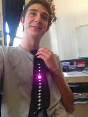
For my main project I made a sound activated LED tie. It consists of a standard issue police tie, 16 Adafruit Neopixels, an Adafruit Flora board, conductive stainless steel thread, a simple microphone and a lithium polymer rechargeable battery. The Neopixels have four holes: a power hole, (marked +) a ground hole (marked -) and two data holes (marked with a small arrows ). The “+” holes are connected to the pin labeled VBATT on the Flora board using a single strand of the conductive thread. Similarly the “- ” holes are connected to one of the GND pins with a single strand. The pins are chained together, that is to say that the top hole of a pixel is connected to the bottom hole of another, using one strand of thread, so that each Neopixel is directly connected to two others but not to the rest. The first is connected to pin D6 on the board. This way the Flora Board recognizes them as single LEDs. Connected to the board is also a microphone with three pins: OUT, GND and VCC. The OUT pin is connected to the D9 pin, the GND is connected to a corresponding GND pin on the board, and the VCC goes to the 3.3V pin to power the microphone. This is the basic breakdown of the electrical components of the tie.
Sewing
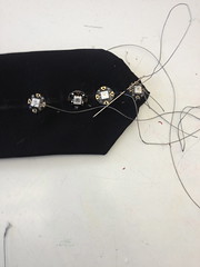
(A picture of the first 4 LEDs being sewn)
All the aforementioned parts are sewn on to a tie. To do this correctly none of the threads should cross or touch. I found that my first attempts at the sewing where ugly and inaccurate. I solved this by drawing unto the tie, using white chalk and a ruler, where everything should be. The Board was sewn to the back of the tie as far down as possible but still leaving enough space for several strands of thread to pass side by side without touching. The actual stitches should cross only one of the layers of cloth, not both, so that they are not sewn together, since this will make sewing the pixels much more difficult. The pixels should be spread out as evenly as possible. I found that if you are new to sewing it is difficult to keep the spacing as it was drawn, so I would suggest practicing on other piece of cloth first. After a couple of attempts I found that it was easier to keep the pixels where I wanted them if the data lines are sewn first, and the power and ground lines afterwards. I had to be careful while sewing the longer lines (power and ground) because if the stitches got too tight the tie would lose its shape. I sealed all the knots with clear nail polish, because it set the thread and prevented it from fraying. I opted to use the conductive thread to sew on the microphone instead of using ribbon wire so that my tie would keep its flexibility. Again I recommend planning out where all the stitches are gonna go, so that two things that shouldn’t touch, stay apart. The microphone was attached to the knot of the tie putting it right next to the speakers vocal cords.
Code
As I was sewing the pixels I would take breaks and test out the pixels I had so far by uploading a “standard test” code. I learnt a lot about coding by simply altering this code, to change light colors and delays. I then created a code that set all even pixels to one color and all odd pixels to another. I expanded this code so that it could be 3, 4, or 5 diferent colors over different pixels. By the time I was done with the sewing I could make simple patterns, so when I uploaded the code for the volumeter from Adafruit industries it didn’t take me long to figure out how to change the colors of the different actions(rising pixels and falling pixels). From there I struggled a bit with making a pattern of colors while the volumeter was active. I was given a lesson on arrays, and when I implemented it, the tie kept on crashing. This is when I learnt about overflow. My array was overflowing because my integer was not large enough to hold the colors and had to instead use the special integer used by Adafruit industries. This allowed me to solve the problem and make it do what I wanted. Over all the tie was a fun project and I ended up learning a lot. Here is a link to my code https://github.com/Esettels14/LED-tie .
Schematic and LED Tie BOM

Conclusion
I have had a lot of fun the past six weeks at Bluestamp. I came to this program with zero experience in engineering of any sort. With the completion of my LED tie I have learnt so much about coding, enough to write my own code for my tie. I faced issues with sewing at first such as spacing and keeping the LEDs in a straight line. I solved this problem by marking on the tie with chalk where it should go. I also had some issues with code like an overflow error when I tried to make an array. It turned out to that my integer was too small and I had to use an integer written by Adafruit industries. Although it was difficult to solve these problems it was also fun. This program showed me a field that I greatly enjoy, engineering. And although I don’t yet know what specific field in engineering I want to go into, I certainly know that I want to go into it. Bluestamp is a great place and a lot of hard work and fun.
My Starter Project Drawdio
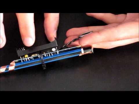
The drawdio is a small device that is attached to a pencil. When thick graphite lines are made with this pencil and one puts their hand not holding the pencil on one side of line and keeps the tip of the pencil on other other side, it will emit a loud pitched noise. What is happening is that the battery starts the current into the system, first it passes a resistor, and this “slows” the current and makes it weaker. It then continues to a couple of capacitors which store the current and then release it. This is to further control the current and voltage. Then comes the TLC551 which is the chip in the center of the board, the 551 is a timer and it oscillates the current between flowing and not. The current flows into a bigger capacitor that fills up and empties as the 551 oscillates. This quick oscillation is what makes the noise, although by itself it is not strong enough to make audible noise. To correct this it then passes through an amplifier and then to the speaker. Then it passes through two more resistors and on to a tab. Copper tape is connected to that tab and is attached to the pencil with a tack so that it is also touching the graphite of the pencil. At the other end is another tab with more copper tape that winds around the pencil to where the hand that is writing can touch it. This tab is connected to the other side of the battery, so when one hand is touching the graphite and the other the copper on the pencil the circuit is complete and noise happens.