Persistence-of-Vision LED Fan
By using a fan to spin a bread board, I would be able to make images by using LED lights. This project would include both programming and electrical skills.
Engineer
Eric C.
Area of Interest
Electrical Engineering and Programming
School
Bellarmine College Prep.
Grade
Incoming Sophomore
Demo Night
Overall, BlueStamp has been an incredible opportunity for me. From learning how to solder tediously to being happy finishing my project, BlueStamp proved to me that it is a once-in-a-life experience.
The mentors were quite amazing. The lead mentors were always energetic and helpful when anyone was in need. The mentors would always lend us a hand to guide us to the right path.
The environment and people made you feel welcomed at the camp, and gave me motivation to keep on persevering to finish my project.
The only negative I had was my constant regret of not attending the full 6-week program. I’m sure that I would’ve been able to complete a more miraculous project.
All I can say is that BlueStamp gave me motivation to seek completing future projects. Thanks!
Final Milestone
After I was finished in making my circuit, I decided that I was going to program the Arduino. Since I never programmed an Arduino before, I had to research the basics of coding a POV fan.
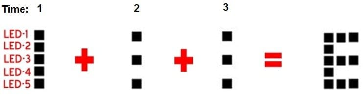
I learned that displaying a character just needed a period of three “points” (unit of time that could be changed). For example, if I wanted to make the character ‘E’, I would have to shine 5 of the lights at point 1, shine 3 of the lights at point 2, and shine 3 of the lights at point 3 (Picture at left to show this).
After I was finished putting numeric values of each points in an array for each character, I was able to store each data. By using a binary conversion function, I was able to change these numeric values into light blinks.
The function is shown below:
if(myLine>=16) {digitalWrite(LED1,HIGH); myLine-=16;} else {digitalWrite(LED1, LOW);}
if(myLine>=8) {digitalWrite(LED2,HIGH); myLine-=8;} else {digitalWrite(LED2, LOW);}
if(myLine>=4) {digitalWrite(LED3,HIGH); myLine-=4;} else {digitalWrite(LED3, LOW);}
if(myLine>=2) {digitalWrite(LED4,HIGH); myLine-=2;} else {digitalWrite(LED4, LOW);}
if(myLine>=1) {digitalWrite(LED5,HIGH); myLine-=1;} else {digitalWrite(LED5, LOW);}
Since I stored each character in an array, I was able to easily write any word with a single change of the code.
After I was finished with my programming, I put my circuit on a fan. However, the fan wasn’t fast enough to display the words/images. Therefore, I decided to switch to a DC motor.
First Milestone
For my two-week project, I decided to make a POV (Persistence of Vision) LED Fan. A POV LED Fan is a circuit board that includes LED lights that spin fast enough to make an image or a word.
To start out with my project, I had to make a Build of Materials and make sure that all my necessities came. After confirming this, I was able to start out with my POV fan.
First, I had to attach the fan to the cake keeper. To allow my fan to have a stable and strong foundation, I drilled 4 holes in the cake keeper and screwed screws through the fan and the cake keeper. After that, I needed some elevation to put my circuit board on the fan. To do this, I super glued 2 blocks of wood on my fan.
Secondly, I needed to make sure that my circuit board (electronics) would work properly. To test, I attached all my electrical components on a bread board. However, when I was testing the PIC microcontroller and when I tried to compile code in the microcontroller, the program wouldn’t allow me to do so. There was 1 big reason why I wasn’t able to fix my bugs/problems involving the PIC microcontroller. Since the PIC microcontroller was released almost a century ago, I wasn’t able to find any resources relating to the microcontroller. Likewise, I had to use a Pick It 2 to code the microcontroller, and the Pick It 2 wasn’t even selling anymore.
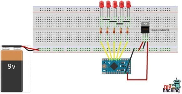
Because of all my troubles involving the microcontroller, I decided to switch to Arduino to light up my LED’s. I realized using the Arduino was simpler, and more time-efficient.
After making my whole circuit board again with the Arduino, I was able to make my LED’s to light up.
By completing making a circuit, I soldered all the components on a board, and zip-tied the circuit to the wooden piece.
My next milestone would be accomplishing coding in the Arduino, that would enable the LED’s to blink in certain times to make words/images.
Starter Project
My starter project was the Big Time Watch Kit, which required the builder to have basic soldering skills and electrical skills.
I started off with researching basic electrical terminology to have a faint idea of how the watch was working:
Resistor: a device having a designed resistance to the passage of an electric current.
Capacitor: a device used to store an electric charge, consisting of one or more pairs of conductors separated by an insulator.
Crystal: A crystal oscillator is an electronic oscillator circuit that uses the mechanical resonance of a vibrating crystal of piezoelectric material to create an electrical signal with a precise frequency.
Microcontroller: small computer on a single integrated circuit. In modern terminology, it is similar to, but less sophisticated than, a system on a chip or SoC
Learning the vocabulary was only part of the challenge, because I was required to extend my knowledge in soldering. One solder after one I was able to overcome all challenges and finish.
Learning the terminology enabled me to finish building the Big Time Watch Kit at 7/9/18. It was a great project to start of with, because it taught me soldering and construction skills. By soldering the components of the watch, I improved my soldering greatly.