
I am a rising junior at Evergreen High School. I wanted to do a project that would be challenging, so I decided on creating a robotic hand. It mirrors the movements of a real hand which is controlling it using a glove with attached flex sensors. I have also created a program that sends it through a cycle of gestures and a program that uses a random number generator to play rock paper scissors.
Milestone 3
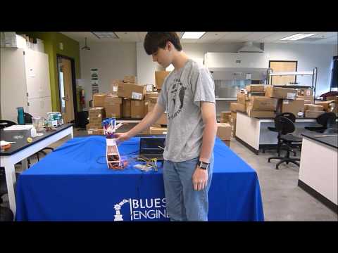
The strings were tensioned to allow the fingers to actually move. They had to be adjusted a few times to get it right. The boards all got mounted to the glove with Velcro, but this is only temporary. I will likely take a piece of cloth and extend the glove down the arm to make more room to mount the arduino, battery and perf board.
The programming had some tweaks for sensitivity and reliability. A rock paper scissors program was also created and a few gestures were added to the servo set program.
PowerGlove – The code used to control the hand with the glove.
ServoSet – Used to set all servos to 0, 90, and 180 degrees for tensioning and testing. Some hand gestures were also added.
RPS – Rock paper scissors using a random number generator. The potentiometer that controls the wrist is used to seed the random number generator.
The circuit has also ha a few changes. A 5v linear regulator was being used to bring the 7.2 volts from the battery down to 5. While it did work, it got hot enough for the air around it to go through nuclear fusion. I didn’t like the idea of something that close to being on fire being attached to my wrist, so it got replaced with a buck regulator. No regulators are needed to get the project working. A 5v power supply from the wall, usb, or a phone power bank works fine, but to use the battery the voltage has to be brought down.

All of the parts for the arm were 3D printed. The files were taken from an open source robotics project called inmoov. I printed the right hand, forearm, rotational wrist, and servo bed for the forearm. I used this as a reference for assembling the arm. It was not followed exactly, but it does a good job of showing where each of the parts goes.
Milestone 2
The wrist and had were assembled. The wrist had a gear attached to the servo and a second gear on the wrist. Both gears were 3D printed. Grease was applied to keep them moving smoothly and to prevent damage since the plastic isn’t extremely durable. Braided fishing line was used to create the “tendons”. Each finger got 2 lines put through it. One in front to contract it, and one in the back to extend it. The joints on the fingers are just 3mm bolts put through 3mm (outside) and 3.5 mm (inside) holes.
A low pass filter was added to keep the signals smooth. Previously everything was run off of the arduino’s power, but after adding an actual power supply the sensors became much more sensitive. The filter takes the previous value and multiplies it by 0.9. After that, it reads the current value of the sensor ten times and takes an average. This average is multiplied by 0.1 and added to the previous value. This number is then mapped and sent to the servo. The averaging takes out most of the rapid, small changes, but by only taking 10% of the new signal it removes almost all of the noise from the signal.
Milestone 1
The majority of the arm is 3D printed. At this point, the forearm is done and the servos are mounted. There are six servos in total. The five servos used to move the fingers are all mounted in the forearm, while the servo used to rotate the wrist is mounted inside the wrist.
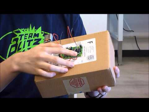
The power glove is just five flex sensors on a glove. They are held on by hot glue and rubber bands at the moment, but that will probably change at some point. Each of the flex sensors in in series with a 10k resistor, creating a voltage divider with a 1:1 ratio. The signal wire is between the flex sensor and the resistor. All of the sensors are in parallel so that they get the same starting voltage.
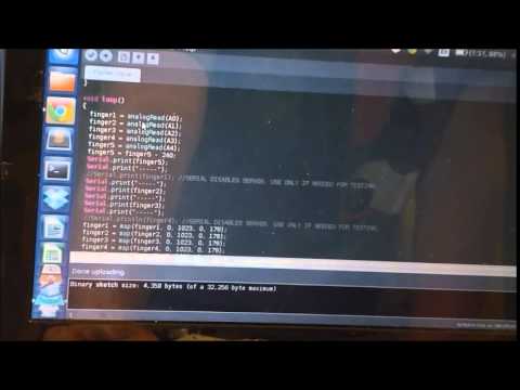
The programming is moderately simple. It assigns 5 analog pins to read the input from the power glove and attaches each of the servos to a digital pin. The analog value from the glove is mapped so that it is between 0 and 180, which is the range of the servo, instead of 0 and 1023. The serial monitor does not work with the servos for some reason, so it is just used for debugging and making sure the values from the glove look normal. After that it gets commented out of the code for actual use.
Starter Project
I made a voice changer for my starter project. It takes sound through the microphone and changes the signal which is then amplified and put out through the speaker. The first potentiometer adjusts microphone sensitivity. It changes the amount of voltage that can be sent back to the input from the output. The second one adjusts volume by acting as a voltage divider to change how powerful the signal getting amplified is. The buttons all allow signals to reach the IC, which does all of the thinking and signal changing to make the sound output different than the input.
After I finished making it, sound did not come out of the speaker. After replacing the IC, the op-amp, and a few other components it still wouldn’t make sound. The problem was an error on the board. The signal for the speaker was shorted to ground. A strip of copper had to be scraped off of the board to make it work properly.