Parkour Light Suit
I have always relished activities such as Parkour, and while having fun, I noticed that I used my hands a lot, and thought it would be cool to see that contact much more literally, and a set of lights that light up upon contact was my perfect resolution to this desire. In making sleeves that light up when a hand hits something held a lot of interest to me and had the potential to make my experience much more fun and exciting.
Engineer
Dylan
Area of Interest
Electrical Engineering
School
Beacon High School
Grade
Rising Junior
Final Milestone
This went great, and at the same time not so great. I did everything that I said I would do, attaching the touch sensors to the gloves and the LEDs to the sleeves, while also reinforcing the touch sensors with more sturdy materials. However, I had this problem where my lights were not lighting up as brightly as it should have. In fact, they were so dim that it was sometimes nearly impossible to see during testing, but still there. As a newcomer to electronics, I had no idea what was going on, but I knew that it wasn’t right. I ran a program that ran both sides at full power, and both lights glowed brightly, as they should. However, when I turned off one of the lights and kept the other one on, both lights idled on this “low glow” as I termed it. I figure that somewhere around the Arduino, wires are touching so that they share voltage. Thus, when both are turned on, they share, and both receive full power, but when only one is turned on, they split the voltage, resulting in a much dimmer effect from both lights. Everything that I wanted to do with the gloves and the sleeves, as you can see in the video. As usual, it’s the stuff that I didn’t plan for that went wrong. If I had just a little more time, and maybe the absence of a pending presentation, I would love to fix it, but the risk that I might irreversibly break it is too large to take. Ironic, that when I finally figure out what’s going on, it’s too late to do anything about it. When I finish everything to my own satisfaction, I’ll update you guys and share my progress. Until then, have a good one!
Third Milestone
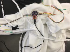
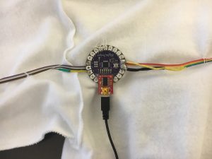
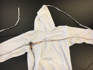
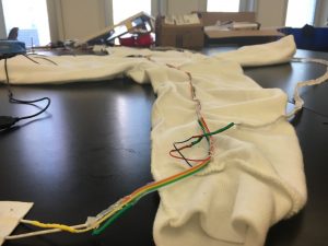
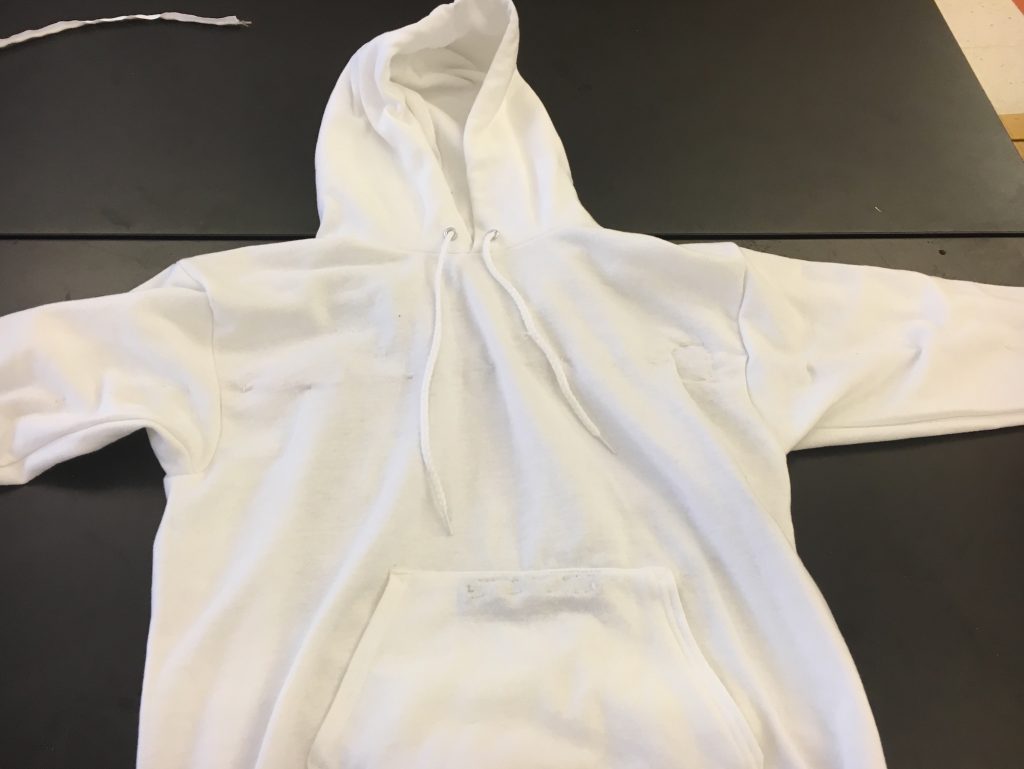
We are very close to the conclusion of the project, and all of the wiring is in place. Nothing has really changed in terms of circuitry or anything. The major changes come in the wiring around the Arduino and in the touch sensor design. With the touch sensor, I had to find a way to keep the two sheets separate at resting state, but touch when I grabbed something, the two sheets would touch. I did this by building a contraption of carefully cut paper and velostat, all of which is attached by double sided tape (as show in the video). At the outset, I thought It was going to be super easy to apply the wires to the sweatshirt, but as you might expect, this was incorrect. Wires that held up fine previously suddenly snapped, and as someone who had never sewn anything before, I had a lot of trouble with that. For example, I had to attach wires to the sleeves, and I found that thread unravels quite easily in some situations and, like the amateur that I am, I sewed through multiple layers, invalidating much of the hard work I had already done. With the sewing, there was nothing to be done but simply redo it all, and I tried the same thing with the wires that snapped, but they simply snapped again. I eventually figured that the stranded core wire that I had been using, while much more flexible and thus suitable for wearables, is much more difficult to manage in a solder joint such as the ones i had to use to interface with the Lilypad, which is designed to work with conductive thread. Instead of that stranded core, I made the wires that directly interface with the Lilypad solid core, then soldered those to the stranded core wires that ran through the rest of the sweatshirt, as is shown in the video. I really didn’t like this milestone, because it was all about repairing stuff that are very difficult to repair, and redoing hard work over and over again. Next, I will attach the touch sensors to the inside of the gloves, and sew the ribbon LEDs to the sleeves of the sweatshirt, and make any modifications that I may want.
Second Milestone
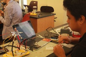
Not much is different between the model you see now and the model you saw in my first milestone video. The wires are in the same place and the software, barring some minor changes is the same. The code was modified so that there were two inputs and two outputs, and I modified my Serial code so that the plotter would plot two different lines for each sensor. Here is where the problems sprang up. I had some trouble turning the single input/output system of my last milestone into a double input/output system, and moving away from the breadboard and helping-hands layout and towards something that can actually be applied to the clothes. This meant a lot of soldering since every single alligator wire shown previously had to be replace with solder joints that wouldn’t break when flexed, and wires had to be precisely the right length to reach down my arm. This is where my main challenge arose. The leads in the LED ribbon, and the colored stranded wires were short and thin – anything but an aid while soldering, and while applying forces that it would undergo in its normal life, these snapped many times over, and required careful resoldering, with that much less material to work with. Another challenge came from the resistors. For the LED ribbon, this was fairly simple, as it was simply in line with the rest of the wiring, and could be relatively securely soldered. However, with the Velostat, the resistor also acted as a voltage divider, splitting the power between the analog input pin and ground. I had mixed feelings about the work up to this milestone. I had a lot of difficulty, and I needed a notable amount of pressure, but in the end, I am happy with how I worked and the end product I created. Sewing the components to the sweatshirt is the next thing to do, and with it an end approaches.
const int ledPinR = 10;
const int ledPinL = 9;
const int tchSensR = A0;
const int tchSensL = A2;
int sensorValR=0;
int sensorValL=0;
void setup() {
// put your setup code here, to run once:
Serial.begin (9600);
pinMode (ledPinR, OUTPUT);
pinMode (tchSensR, INPUT);
pinMode (ledPinL, OUTPUT);
pinMode (tchSensL, INPUT);
}
void loop() {
// put your main code here, to run repeatedly:
sensorValR = analogRead (tchSensR);
sensorValR = map(sensorValR, 0, 1023, 0, 255);
Serial.print (“right = “);
analogWrite (ledPinR, sensorValR);
sensorValL = analogRead (tchSensL);
sensorValL = map(sensorValL, 0, 1023, 0, 255);
Serial.print (“\t left = “);
analogWrite (ledPinL, sensorValL);
Serial.print (sensorValR);
Serial.print (“,”);
Serial.println (sensorValL);
}

First Milestone
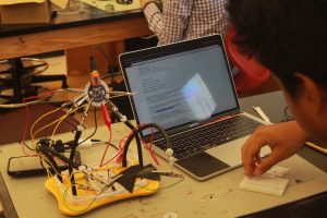
My project is a design that revolves around my engagement in physical activity. It is a set of gloves that is attached to a sweatshirt. The reason for this is that my creation is a device that will translate plam contact into the brightness of certain LEDs attached to the sweatshirt. This is a documentation of my first milestone on the way to this end goal. I had basically divided the project into three parts: working on the LED ribbon-Arduino and the Velostat-Arduino interface (I’ll Explain), the combination of these two components, and the application of these components to the actual clothing. This video announces the completion of the second step. On to how it works. It looks kind of complex, but that isn’t really the case. The two fore said components are only connected through the Arduino and can be treated as independent systems for the purposes of this video. First, the LEDs as this is a little more simple. For this, the cords that connect to the Arduino board are red. One cable connects to pin 10,which is also a PWM output pin, which would allow for a fade effect. The current runs through a 470 ohm resistor and out to the ground. Next, the Velostat system works much like a button. Velostat is a variable resistor, but it’s readings are really inconsistent when a circuit is closed. However, the solution was revealed. By hooking up two pieces of velostat to make an open circuit, we can control the readings more consistently. This is because at natural state, the circuit is open, and is always outputting a value of 1023. This is changed however when the two sheets are made to contact each other, closing the circuit. The current runs through the variable resistor, then out and through a 1k resistor, which splits the current between the VCC connection and the input pin A0. The code is not that complicated either. It simple reads the value coming in from the sensor, stores it, then uses that value to indicate the brightness of the LEDs. I had many challenges, chief of which was figuring out how to make the Velostat work. After the solution stated above was adopted though, These challenges pretty much disappeared. Next, I will design a system to incorporate another set of Velostat and lights, and apply all of it to the actual clothing.
const int ledPin = 10; // defines led as the PWM pin D10
const int tchSens = A0; // defines analog 0 as the touch sensor
void setup() {
// put your setup code here, to run once:
Serial.begin (9600);
pinMode (ledPin, OUTPUT); //sets led as output
pinMode (tchSens, INPUT); //sets touch sensor as input
}
void loop() {
// put your main code here, to run repeatedly:
int sensorVal = analogRead (tchSens);
sensorVal = map(sensorVal, 0, 1023, 0, 255);
Serial.println (sensorVal);
analogWrite (ledPin,sensorVal);
}

Explanation
Here's What It Means
This is the schematic for the single input/output system that I built while achieving this milestone, in which the red wires are power, black wires are ground, and the orange wire is the analog input. The Yellow wires are just connective wires. As is shown, there are effectively two different systems attached by the Arduino board. The LED system runs power from the digital pin through the resistor, the LED, then finally, back through Ground. The Velostat system conducts current from the VCC pin instead of an output pin, then runs current through the sensor. The power then flows through the resistor, which splits the voltage. one part continues on to the Ground pin, while the other goes to the analog input pin, providing information.
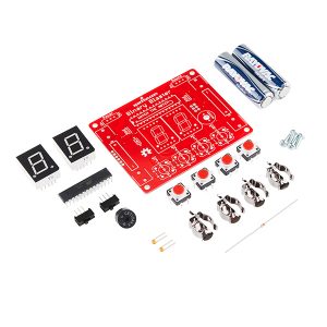
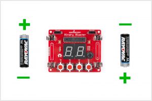
Starter Project
Everything starts with the battery clips and two 1.5V AA batteries, which provide power to the entire device. The current then flows through the resistor, which resists the electron flow and prevents excess current of overcharging and damaging other components of the device. It also flows through the resistors, which also protect the other components from damage. They smooth the voltage by slowing the rate of transient voltage change that could overwhelm the resistor and damage components. This is achieved by storing excess energy so that only a small rate of change is achieved. From there, the current goes through the microcontroller, which is the brains behind it all. It is much like a processing unit in any other computer, but much cheaper, slower, and simpler. It, unlike a conventional CPU, is only designed to do one thing, and thus the amount of programming is much lower. The current goes into the microcontroller and interacts with this code, which then tells the various lights when to light up, and thus the device works. My first problem was with the tactile buttons. With these, orientation matters, because the polarity of the button controls the light, an integral part of the system’s function, and if the polarity is incorrect, the light will not work. This happened to me, and when I attempted to desolder the button and flip it, I was unable, due to, as I postulate, the bent nature of the button’s pins. When I was unable, we tried another solution; cutting certain traces and attaching other pins in an attempt to reverse to polarity without reversing the button. However, after we did this, the device wouldn’t turn on, much to my despair. I tried to fix this by rewiring it back to its original configuration, but once again the lights refused to light up. Generously, Lead Instructor Ayo provided me with another Binary Blaster Kit, which I assembled as flawlessly as I could, but the new one also didn’t turn on. A simple fix is actually shown on the product website, in which you join two jumpers with solder and cut a trace. We soon discovered that there was nothing catastrophically wrong with either model, but the battery clips were simply loose and with the right pressure applied in the right places, both models functioned properly.
Awesome Dylan!!!! Can’t wait to see the next step!
I can tell you I read and watched Your invention and I’m totally amazed.
By the second time I grasped the concept.
Yes it is a motivator. Ruth
Proud of you. We might have a genius inventor in our family. And so handsome!
Wow that’s so cool