Introduction
Hello, my name is Duncan. I am a rising senior, interested in math and science. I am building a TV-B-Gone device and a balancing robot. I hope that this experience will help me learn the uses of the components and have some fun while I’m at it.
Drew: This is my high school.
BOM: My Bill of Materials. Everything that was used in my project can be found here.
Code: Every piece of code I used to make the robot balance.
Blog Reference: The initial idea came from this blog.
Final Video
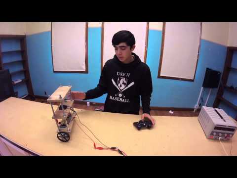
Considering how hard my project was, and how ambitious I was to take it on, especially with almost no previous coding experience, I am very happy with the final product. That is, it successfully balances, stays in one spot, and moves, although not smoothly. Every milestone I hit only revealed an even more difficult task around the corner. After I finished working with the IMU, I had to get it to balance. While balancing was hard, the majority of the process was guess and check. After that, I had to make it stay in one place. Even after that, I had to work with the controller, which was definitely the hardest part.
When trying to control the robot, I had to come up with a logically sound way bringing it up to a requested speed. By logically sound, I mean it had to both do the requested task (in this case, moving), and do it smoothly (without jerking around). As easy as that sounds, I had many logical ideas that simply didn’t work because of imperfections or inadequate transition states. This is when a change in the requested speed makes the motor output jump from one value to a much different value, and the jump destabilizes the robot.
My first idea was to either add to or subtract from the actual angle. If the robot thought it was at 90°, but it was really at 88°, it would start to move! Unfortunately, that is just too simple to work. I ran into a wall when I predicted that I would need to remove the PD position control from the equation. If all of a sudden you just drop a factor, the motor output will jump from one value to a very different one. It was too unstable of a system.
My next idea was to change the target position. Let me explain. The way I had the robot balancing and keeping it still was through a position control. If the robot was past the target position, its response would be to tilt toward the target position, moving it back there.

But what if the target position was constantly moving forward? Well, the constant response would be to “catch up” to the target position. The first problem I ran into was the derivative control in the PD position loop. I was using both the position and the velocity to keep the robot in one place, so changing the target position and not the velocity put them out of sync. They were both aiming for different targets. So I created a “target velocity” from the target position, so the entire PD control would be in sync.
Milestone #2
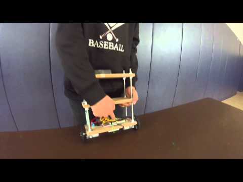
My second milestone was only about getting the robot to balance on its own. Even though all the electrical components were hooked up in the first milestone, the robot was not at all close to balancing.
I found a block of code online to run the IMU (accelerometer and gyroscope), the logic of which was way above me. I then took the raw accelerometer and gyroscope values and computed the angle that the robot was at (90 being perfectly balanced, theoretically). The reason that I needed both the accelerometer and the gyroscope values was because they complemented each other. The accelerometer had a constant, definite direction to anchor to, which would be straight down this made it very accurate in the long term, because it was unnecessary to actually compute the angle. All I had to ask was: “where is straight down?” However, the values it gave were very discrete. Simply put, it’s values changed in very large steps. The gyroscope, on the other hand, was practically continuous. It gave values that changed in very small steps. However, the number it produced was only the change in angle. Adding up all the past changes in the angle gave me the actual angle. The only problem was that the gyroscope did not have any way of telling me where straight down was, I could only compute it. So if I combined the gyroscope and the accelerometer, I could get a reading that was both continuous and accurate. The actual function for filtering the values was:
angle = 0.99 * GyroReading + 0.01 * AccReading;
This is, of course, a somewhat simplified version of the methods I used, but it gives a general idea of how it worked. Note how the GyroReading has a much bigger weight than the AccReading. That is because the GyroReading has a higher resolution, its steps being much smaller. The AccReading is only 1% because I only need it to help keep the notion of “straight down” accurate, as the Gyro’s angle alone would drift off slowly.
After I took care of the angles, I had to actually do something with them. The arduino had to be coded to give a response Output to the motors, and right the robot. My initial ideas were to create a mathematical function, either algebraic or trigonometric, to keep the robot balanced. The objective with this is to create a function that reduces to zero at 90°, but increases with the right curve in both directions. I worked with square roots, sinusoidal, linear, and power based functions.
After chugging away at the math for a few days, I felt that my robot was far from perfect. This prompted me to change to a PID control system, which stands for proportion/integral/derivative. Using calculus, this system can adjust the real output to meet the target output. I spent a while trying to work this out, but in the end, the robot was too unstable to work with the PID. In other words, a PID is good if your system isn’t constantly tipping over.
After giving up with the PID loop, I went back to pure mathematics. The function I eventually came up with was a sine function, with a twist. The entire function was this:
Output = -sin(Input * 2 * pi / 180) * 255 * 4.25 * sin(Input * pi / 180)
It is a lot to look at in equation form, but here is the function on a graph:

The point at the bottom is 90°, and it starts sharply upward but curves off. Another nice aspect that was sort of a surprise was that the function decreases to zero at either 0° or 180° (when it’s lying flat). So, if the robot were to tip over, the motors would automatically turn off.
The second part of this milestone was getting the robot to stay in one place. In a nutshell, it would start tipping and run away, eventually falling over. The actual mathematics behind this is more complicated. Basically this was a huge problem, because I don’t want a robot that just runs away every time it reaches perfect balance. So I decided to use the encoders on the motors to try and counteract the drifting.
I created a PD control, which is using only the proportion and derivative from the PID, to make the robot stay still. Using the relative position and velocity from the encoders, I made a function which would return the robot to the same spot every time it started to drift. The end product was a very slightly unstable robot that would oscillate minimally, in a range of about 10 centimeters.
Milestone #1
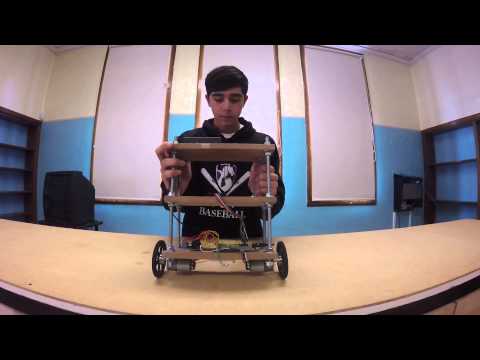
This milestone represents the construction of the frame and all of the components necessary to get the machine to balance. This includes obtaining the angles from the gyroscope on my robot and getting a response from the arduino. There was some difficulty in just doing this though.
The biggest issue was there was no way to find a code for the gyroscope that was configured for the Arduino Due. I searched for a long time online and in past students’ work, and eventually found a working modification through the work of a previous bluestamp student. I was lucky that someone before me had figured out the problem, because it involved code I am not at all familiar with.
After finding this code, getting the angles was simple. And once I had the angles, I could easily run it through a mathematical function to obtain a motor response. I used two PWM (pulse width modulation) to set the speed of the motors, and four other digital pins to control the direction of the rotation. Pulse width modulation basically mimics an analog pin, allowing one to send a signal that can act as a slider. While digital pins can either be on or off, PWM pins can be anywhere in between.
Starter Project
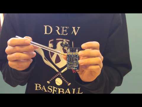
My starter project was a TV-B-Gone device. It sends out a bunch of universal infrared signals for the power function in TVs. I was interested in making it because it would be a devious tool to have.
During my process, I learned what an ceramic resonator, a ceramic capacitor, and an electrolytic capacitor was. I also learned the difference between an NPN and a PNP transistor. I had self taught myself how to solder before, but I was very inexperienced. I learned the proper technique and good experience in how to solder by making this device. Even though this is basic electronics, understand the properties of each component helped me greatly to gain a little electronic know-how.
Furthermore, I found out that my camera can pick up the infrared wavelength that the device emits, and it’s totally cool to look into my camera and see the light flashing that, with my bare eyes, I cannot see. I can’t wait to use this device, for good or for evil.
Duncan,
Very impressive. Does it have a name?
Please post your code and the IMU libraries you used (FreeIMU?) RTIMU?) and the modifications.you mentioned. Did you have a particular reason for choosing the Arduino Due?
In my experience, the hardest part is what I call “kit bashing” or the actual physical construction of the damned thing. The coding is pretty easy, although I have found that the whole “libraries” business with the Arduino IDE can be somewhat difficult to figure out (AVR Libraries, Contributed Libraries, Sketchbook Libraries, etc.).
I look forward to seeing more about the PS2 interface you mentioned.
Best regards,
Bud