
Engineer
Ivan G
Area of interest
languages\civil engineering\ math\ physics
School
High School №552
Grade
10

In the end
I would like to thank the BlueStamp team for being so friendly, helpful, and interesting. i’m so happy that I had an opportunity to go to the BlueStamp camp because there I got knowledge which will be very necessary in my future career also I made friend with a lot of different and very interesting people… Thank you, BlueStamp!
Final milestone!!!
What is it?
I finished my project! For my final milestone I assembled my Arduino Uno, Adafruit Neopixel, power supply, wires together and attached them in wooden box.
Figure 1

What i learned
Now i know what to do with project components if there is not enough space, where and how to attach them in that case.
How i made it?
I decided to attach Adafruit Neopixel 8×8 in the center, so i could understand how and where attach other parts of my project. Then, I attached Arduino Uno to one of the wooden box walls because there was not enough space to attach that next to Adafruit Neopixel 8×8. For power supply i had to make a hole which goes through wall next to the Arduino Uno. Then when everything was completed, I energised electrical components and I realised that some wires blocked the light between diffuser screen and Adafruit neopixel 8×8, so i decided to glue wires to another wall.
Figure 2

2 milestone
What is it?
In the second milestone I made a window in the box, painted it white and also made a diffuser screen.

What i learned
This milestone was very mechanical in nature. I learned how to use the drill and circular saw. Also i learned how to painted more properly and carefully.
How i made it?
I made a window with a the small circular saw called a Dremel. This was very good choice for cutting wood.
For the diffuser screen, I measured the size of the window and the diffuser screen fit perfectly.
To make it look fancier and nicer for my home, I painted it white color so that it will be pleasant while staying in your room.

Main project: Led Fireplace
1 Milestone
What is it
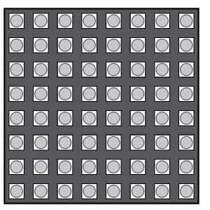
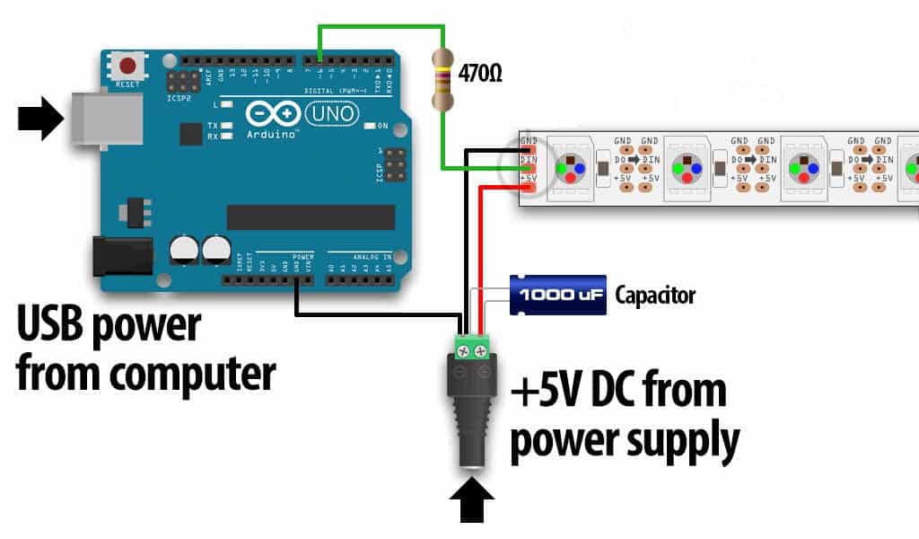
For my first milestone I connected an Arduino Neopixel 8×8 (figure 1) Uno with Adafruit
Neopixel and 5V power supply.
It includes Arduino Uno, breadboard, Adafruit Neopixel 8×8, power supply.(figure 2)
Each of this components connect with each other and work together to make a fireplace

Mistakes
That was quite challenging milestone, since I first used Arduino Nano and my computer was not able to see computer port connected to that device so I switched to Uno.
How it works
To make it work, I connected the power supply, in this case it was an anker powerbank.The powerbank supplies 5V in order to energize adafruit neopixel 8×8, the lights. Current also goes through Arduino Uno. The Arduino Uno is a microcontroller. A microcontroller is a compact integrated circuit designed to govern a specific operation in an embedded system. Integrated circuit is an electronic circuit formed on a small piece of semiconducting material. Here the microcontroller operates as the brains of the my project. I code the microcontroller to control the project.The Arduino controls lights in a special order to simulate a fireplace.
To create the illusion of a fireplace, the lights must not just light up but also turn off. For this, it is necessary to program the Arduino.To do it you should download the special libraries order to make working code. These libraries have specific functions ready to use for the matrix. For my project i used these: Adafruit_NeoMatrix and Adafruit_GFX.
Then it’s necessary to have a right code. I used this: https://docs.google.com/document/d/1RHjiV87sZBOndN5lKm4kAJGrCkekQxgFFI0L2R9_ouo/edit?usp=sharing
Special commands create a special sequence of the lights such as:
Return – which ends a function
Strip.setPixelColor – which set particular color in the adafruit strip of lights
ColorWipe – this command delete the color we chose
Delay-which makes the Arduino go to sleep a particular quantity of time.
Colors are a transition r-g-b – refers to a system for representing the colors to be used on a computer display.
Void – it indicates that the function is expected to return no information to the function from which it was called.
j-=6; i+=6 – particular coordinates of the light
Int j = 0; j < 256 ; j++ -this is how we loop through the RGB information values
starter project: Mintyboost
My starter project is Mintyboost Charger (https://www.sparkfun.com/products/10094), a small charger for your phone (iphone or android) which use AA batteries. It was created to keep your phone alive when you really need it
Demonstration
How it works?
All that it uses two 1.5V batteries which you put in battery holder. The MintyBoost is really a boost converter. A boost converter is a DC-to-DC power converter that steps up voltage from its input to its output. A boost converter circuit can be in figure. A boost converter has an inductor and a diode. An inductor is an electrical component that stores energy in a magnetic field when an electric current flows through it. A diode is a two-terminal electronic component that direct current primarily in one direction. The boost converter is controlled by an IC chip. Basically, an IC chip is an assembly of electronic components, in which miniaturized active devices (e.g., transistors and diodes) and passive devices and their interconnections are built up on a thin substrate of semiconductor material. Current from the batteries goes through the resistors in order to increase voltage. Phones usually use a 5V charger. That’s why i used boost converter so that i convert 3V from the batteries into 5V which needs to charge my phone. The two electrolytic capacitors use to smooth input and output voltages, so that it keeps stable while energy transfer. Construction locate into small iron box which serves as a frame.
What i learned?
Now i know what resistors, boost converters, electrolytic capacitors and diodes are and what they were made for. Also I learned how to solder metal and PCB components together.
