
Introduction:
Hi! I am Divya, a rising sophomore at Saratoga High School.
For my starter project I built a Minty Boost phone charger. Using a schematic I found online, I soldered all the components provided in the kit onto a PCB board. When connected by USB, a phone will be charged.
My main project was a hand-gesture controlled robot. Flex sensors are attached to a glove. When flexed or bent, they send a number through an Xbee, a wireless communication device. A receiving Xbee is on the robot, which will do certain functions based the data received.
Link for Starter Project (Minty Boost):
http://www.ladyada.net/make/mintyboost/solder-v2.html
Link for Main Project (Hand-Gesture Controlled Robot):
http://www.instructables.com/id/Handgesture-controlled-robot-with-robotic-arm/
Reflection:
My favorite part of Blue Stamp was the guest lectures by real engineers in the industry. I thought it was really cool how every person that came had a completely different story but, were all participating in really cool projects that could potentially impact a lot of lives. During my experience in Blue Stamp, I realized I for sure wanted to go into the tech industry. I am interested in robotics, electrical engineering, and computer science. What I took away from Blue Stamp was my love to fix problems. It is the most exhilarating feeling being stuck on a problem for days or weeks but then finally solving it after hours of research.
My Main Project:
My main project is a hand-gesture controlled robot. Below is all the information you need to build my project including my documentation!
Final Video:
Do It Yourself:
Learnt:
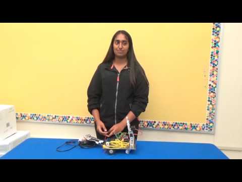
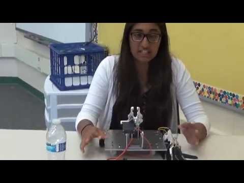
In my final video, I have my hand-gesture controlled robot. Since the last milestone, I created a circuit for my two servos. The flex sensors output values onto the arduino on my glove. An arduino is a microprocessor or small computer. The values get sent wirelessly to an arduino on the robot through wireless communication devices called XBees. Based on the values being received, the arm and claw open and close. I also tried making a circuit for my two motors however, they didn’t work. I hope to eventually make the motors work.
Milestone 2:
Learnt:
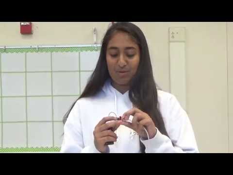
In my second milestone, I made the robot and the glove. First I had to get my metal base cut. Then I drilled holes into the aluminum for wheels and the claw. To mount the motors I had to use hose clamps. Then I made the glove. I had to learn how to sew. I sewed the flex sensors onto the glove and put electric tape for extra support. I then attached wires to the ends of all the pins on the flex sensors. The wires led to power, ground and analog. I soldered the wires together and plugged them into an Arduino. Then I attached the Arduino onto the glove using velcro.
Milestone 1:
Learnt:
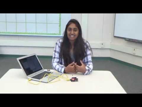
In my first milestone, I made a light turn wirelessly using xbees. I, first had to configure the xbees which took a while. Then I had make a circuit that turns on a light. I coded program that when given a certain input it turned the light on and off. I typed a letter into my computer which was sent to the other xbee which was connected to an arduino. The arduino had the code and read the input. The specific input then turned the light on and off.
Starter Project:
Learnt:
For the starter project I made a phone charger or MintyBoost. This project required a lot of soldering. I learned about the different functions of the electronics in my project like capacitors, resistors and diodes. I also learned what an electrolytic capacitor and boost converter chip does. Overall, the project was successful and I learned about many different electronic components.
Explanation:
I started by soldering 3 different kinds of resistors onto the PCB board. Then I soldered two capacitors which stabilized the voltage. After I added the diode which makes sure energy is transferred in the right direction from battery to USB. I then added the IC socket which protects the boost converter chip. Then I added the Power Inductor which stores and converts power from low to high voltages. I, then added the electrolytic capacitor which keeps the voltages stable while the project is running. Then I soldered the battery holder and USB port. Then inserted the boost converter chip and batteries. Originally it didn’t work because it wasn’t recognizing it as a charger so I later had to solder two USB pins together.
Parts:
PCB Circuit Board – Board where I connected all the electronics
3.3k resistor – Improves high current capability of boost converter chip (non-polar: doesn’t matter the way you place it)
75k resistor(2) – non-polar
49.9k 1% resistors (2) – They determine what kinds of charger is connected to them
Capacitors(2) – 1. Stabilizes the output voltage and filters out noise so the output is nice and smooth 2. Stabilizes the internal reference of the boost converter chip keeping the chip stable so it will produce the most precise voltage (non-polar and symmetrical)
Diode – Makes sure energy is transferred in only one direction (from batteries to USB port). Current can only pass through them in one direction
IC socket – Protects the chip and allows for replacement of the chip
Power Inductor – used by the converter chip and allows to store and convert power from low to high voltages ( non-polar)
Electrolytic capacitor – keeps voltages stable when project is running
Battery holder – hold the batteries
Boost converter chip – It converts the input voltage to the output voltage.