
The Robotic Hand
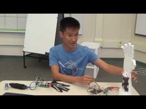
My name is Davin and I am a rising junior at Lynbrook High School with a passion for engineering. My project this summer is the 3-D printed robotic hand, inspired by this website. This is my final project:

Reflection:
Although the program was six weeks, it definitely didn’t feel like it. The experience of having your own project to work on when you get there, that you can do what you want with your time as opposed to a structured class made the time fly. Even though the build for my project went relatively smoothly, I of course encountered many problems anyway. Perhaps the largest struggle of the project was trying to get the RF24 modules communication wirelessly between Arduinos. After three days of getting nowhere, with two of the instructors helping me, we found that using the pi instead was a better solution. As someone who is very quick to identify the problem/debug, this whole ordeal taught me something I didn’t expect: that sometimes problem solving is about solving what is right in front of you, but rather dodging it with either a work-around or compromise. During the project, I thought I regretted picking something that had so little to do with software, as that was both what I am interested in and what I am good at. But now I realize that getting familiar with the mechanical/electrical side of engineering is also a worthwhile experience.
Final Milestone:
For my final milestone, I added a number of modifications to the robotic hand.
First of all, I mounted all of the electronics on either the robotics hand or the glove, making it so I only have two loose parts, which is as good as I can get. In addition to the batteries, I added an on/off switch to the power cable. This way, I can leave the arduino/pi plugged into the battery, and when I want to turn it on, I simply flick the switch
I also added a way to “record” an autonomous routine. When you start the arduino, you can press a button to record a 20-second routine. Once the recording is done, you can press that button again to run it however many times you want to. To make it easy to debug without plugging the arduino into an interface, I attached three LEDs to show the state of it. The green is lit when the transmission is successful, the amber is on when it is running an autonomous script, and the red is on when it is recording.
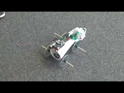
I also added wheels, which are mounted with two 1/2 inch diameter wooden dowels. The wheels themselves are 4-inch in diameter and acrylic. The brakes are done with a small servo that can be controlled in place of the thumb. Here are the drawings for the wheels and the dowels:
Here is the final code for the project:
https://github.com/dtjong/RoboticHand
Here is the schematic for the electronics:

and here and the 3-d printed parts for the hand:


found on this website:
http://theroboarm.com/overview.html
Here are all the materials I used:
https://docs.google.com/spreadsheets/d/1b0TbrdwvGf3lWkDx3Q0bRpw8amtUo6Q6fjdAxn72dw0/edit#gid=0
Milestone 3:
For my third milestone, I implemented wireless communication between the glove and the robotic hand.
To accomplish this, I used a cheap wireless module called the RF24. Because these didn’t work from Arduino to Arduino, I used a Raspberry pi instead. Here is the python code I used for the Raspberry pi. The initial “three lines of code” I anticipated the receiving code turned out to be a wrong estimation. That said, this code simply listens for another RF24 module, and relays the signal to the GPIO pins connecting to the servo. The only “problem” I encountered with using the pi for this purpose is that the pi only has digital output, while servos need an analog signal. Thankfully, pwm (pulse with modulation) is readily able to implement on the pi. Pwm simulates an analog signal by rapidly turning the pin on and off.
This is the final code for the Arduino. It is the same as the code I finished in the first milestone, but at the end, instead of writing to a servo, it writes to the radio. One of the major problems I faced doing thing was the fact that the range of values I needed to give to the pi were different then what I would give directly to the servos. The servos take in a 0-180 value, while I found out later, through breaking of the hardware, than the way I had pwm set up, the range was more like 7-60.
Here is the code for my project: (the raspberry pi code is in the NRF24L01 folder) https://drive.google.com/open?id=0B3DFkjy4j5qTelVXZWZLWnZCbWM
While the project is pretty much done, I intend to add various modifications to it, such as wheels and perhaps an on-off switch. I also fixed the wires not too look as messy and mounted the Arduino on the glove.
Milestone 2:
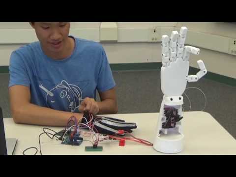
For my second milestone, I completed assembly of the hand and connected it to a glove with flex sensors attached.
The hand itself is made out of 3-D printed parts. Each finger has two strings attached to it to actuate them. When the string on the front side of the finger is pulled, the finger is curled, and when the string on the back of the finger is pulled, it is straightened. The strings are attached to a servo controlled by the Arduino.
The glove has four flex sensors on it (pinky and ring finger are grouped together), and they are mounted on the glove by covering them in a layer of duct tape, and sewing the sensor by the duct tape to the glove itself.
After this, the original project was “done”, but many improvements were still to be made. I went through and sanded all of the joints that were prone to getting stuck. The contact between the wire on the flex sensors weren’t good, so I had to solder them. I reconfigured each servo for a full range of motion by moving the part that spins to be vertical by default, and tinkered the code to go all the way.
For the final milestone, I will work on making this work wirelessly with xBee Arduino shields.
Milestone 1:
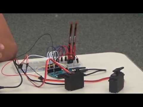
For my first milestone, I finished all of the wiring for the robotic hand, as well as the code controlling it.

The project so far reads in values from the flex sensor, and the servo moves based on it. The Arduino sends 5V of electricity through each of the flex sensors, and the Arduino reads the output. The flex sensors are essentially resistors that resist more when they are bent or flexed. The signal of the flex sensors is also connected via 22k ohm resistor to ground because the flex sensor is a variable resistor, so the Arduino can the difference in voltages between the two to get a reading. The signal then goes through the Arduino, which in turn sends a signal to the servos.

This is the code for the Arduino. Each individual servo is initialized at the top, along with two arrays for storing values. The values for the flex sensors read from the analog input are stored in the array flex[]. Then, each tick (every tenth of a second), each value of flex[] is updated, then each value is normalized and stored in the array angle[]. The reason normalizing is necessary is because Arduino’s servo library takes in a number between 0 and 180. Then, each angle[] value is written to its corresponding servo.
Starter Project
For my starter project, I chose the Simon Says game because it taught me how to solder, as well as warmed me up for creating stuff with various electronic parts. The game works by giving you a sequence of button presses, and then you memorize it and input it yourself. If you mess up, the game ends. There are various electronic parts involved. The logic is controlled by a microcontroller, the sound is created by a piezo speaker, and the blinking lights are LEDs. The white rubbery layer has buttons built into it, and there were also resistors for controlling current, and capacitors for storing electricity.