This is a GPS tracker that is connected to a cellular data network. The tracker uses an Arduino and a GPS/Cellular shield. Every 10 seconds, the tracker uses its LTE cellular connection to send GPS data to thingsboard.io, an advanced IoT dashboard that can show the tracker’s location, speed, altitude, and a variety of other stats. The tracker can be used to track the location of many things, such as cars, bikes, backpacks, and people.
Engineer
Daniel L.
Area of Interest
Computer Networking
School
Gunn High School
Grade
Incoming Junior
Modifications
I put the tracker inside a Pelican G40 case. The case is waterproof and dustproof and is barely wide enough to fit the tracker. The tracker won’t rattle around inside the case since it can barely fit. I can also store a couple of small items inside the case. For now, I put the chargers for the lipo battery and the power bank inside the case.
I also duct taped the lipo battery and the tracker together to keep it compact. I put a small piece of cardboard between the tracker and the battery, to protect the battery from the sharp solder points on the Arduino.
Final Milestone
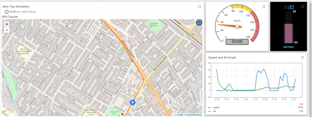
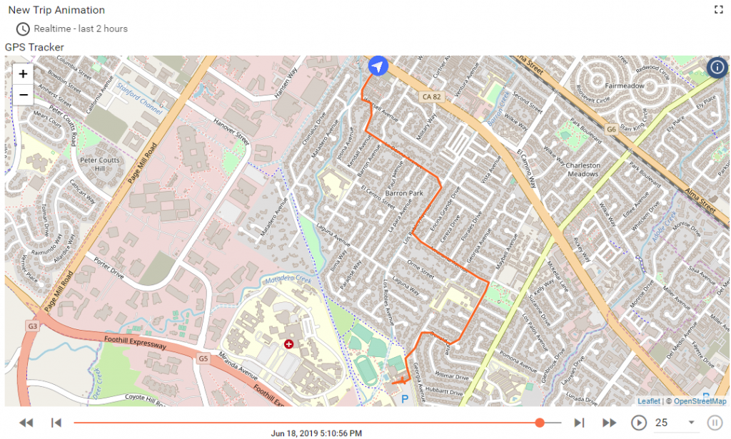
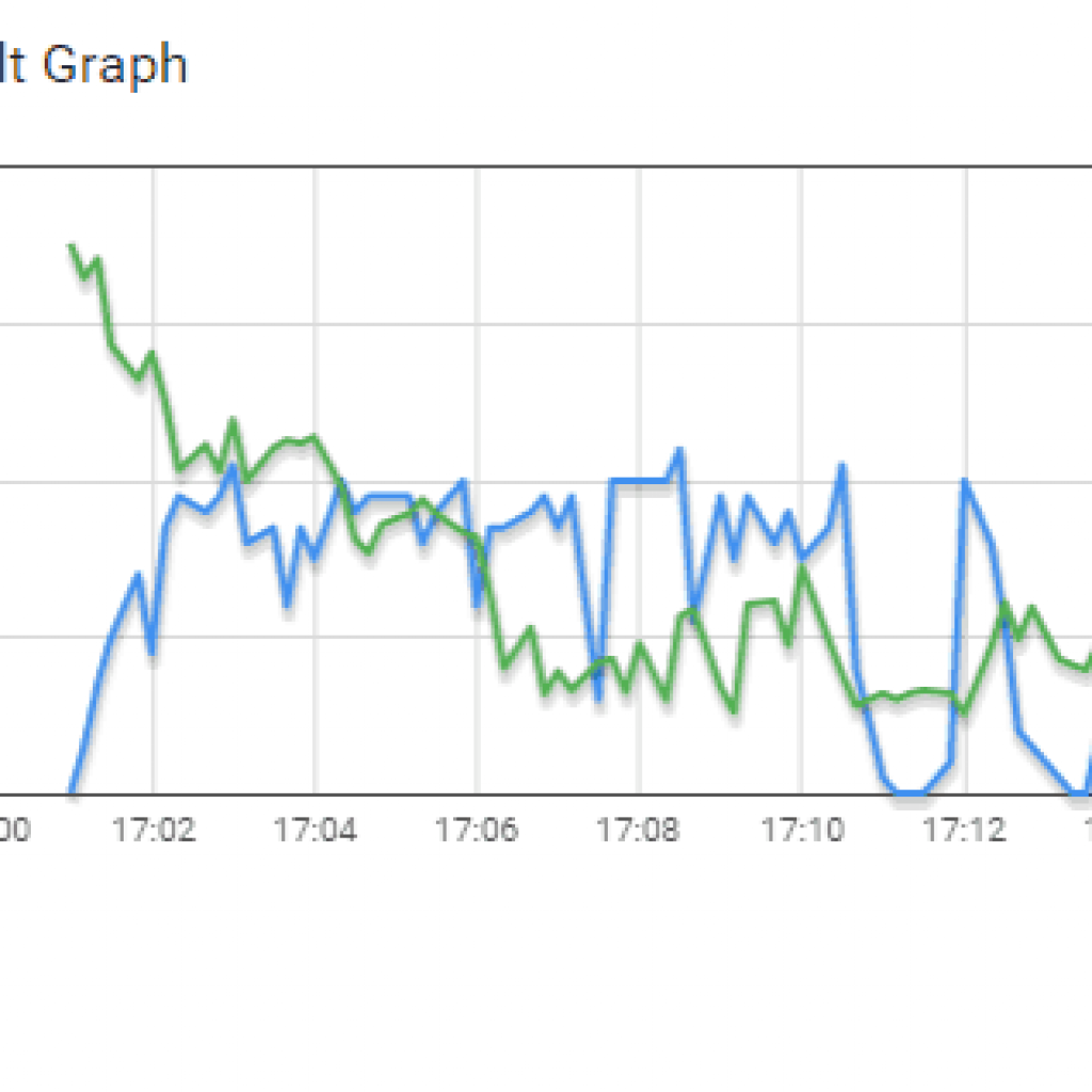
My final milestone is getting thingsboard.io fully setup and useable. Thingsboard.io is a more advanced IoT dashboard. The tracker will send data directly to thingsboard, instead of using dweet and having freeboard extract the data from dweet. Thingsboard can also store data on their servers, which means I can see past location history in the last 30 days. I added an OpenStreetMap pane, gauges that show speed, altitude, and the signal strength of the cellular connection. I also added a graph that shows speed and altitude over time. Setting up thingsboard was just as easy as setting up freeboard.
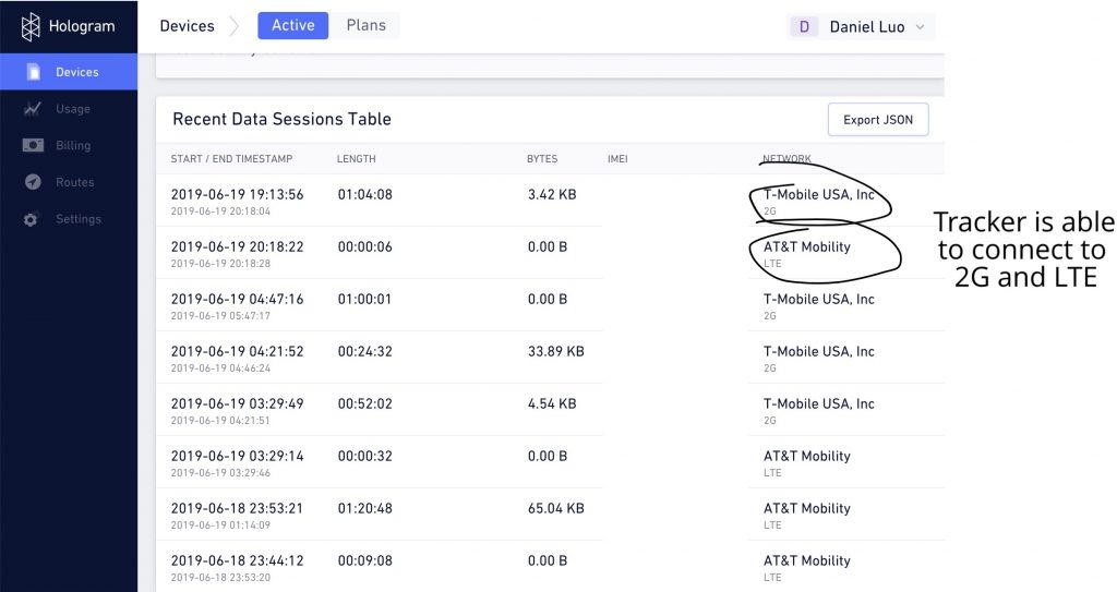
I was also able to get the tracker to connect to the 2G network instead of LTE CAT-M1 (LTE CAT-M1 is not the same as the LTE frequency used by smartphones, and only the US has a good CAT-M1 network). This means that the tracker will still network when LTE CAT-M1 is not available but 2G is. Many other countries do not have an LTE CAT-M1 network, such as China. If the tracker were in China, the tracker would use the 2G network and would still be able to operate.
For my test runs, I put the tracker on the dash of the car when I was driving, and I put the tracker in my backpack when I was biking.
Driving and Biking with the tracker
Testing the tracker at Gunn
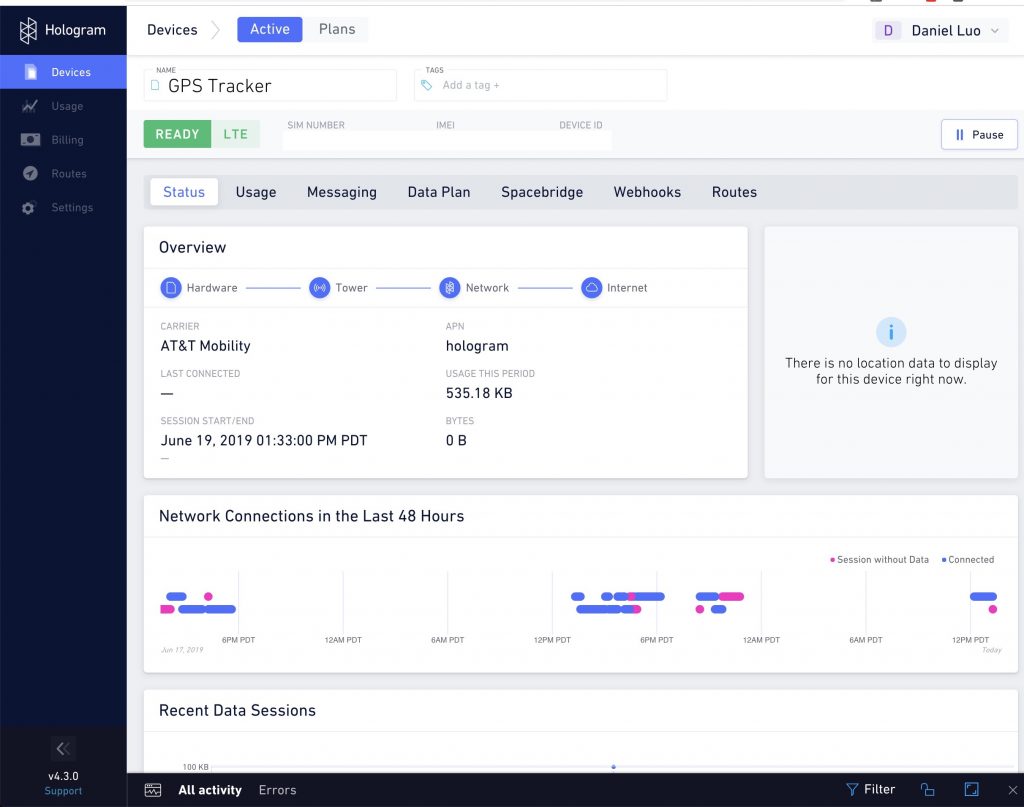
Hologram Cellular IoT Dashboard
Third Milestone
Drive test using freeboard.io
My third milestone is when I set up freeboard.io and it would show the path of the tracker as it moves around. I did this by setting up a freeboard account, then adding a datasource to my board. I set the datasource to the tracker’s dweets, and freeboard was able to extract the data from dweet. I added a Google Maps pane, and set the map to extract the coordnates from dweet. I also added gauges that show speed and altitude.
The only thing is that freeboard will not store past location history, and reloading the webpage will clear the path on the map.
For my test runs, I placed the tracker inside the cardboard box that the power bank came in. The power bank couldn’t fit inside the box alongside with the tracker, so I ran the cable outside the box and had the power bank on the outside.
Bike test using freeboard.io
Second Milestone
My second milestone is when I got the tracker to post GPS coords to dweet.io. I did this by creating a new Arduino project and using the Adafruit FONA library to tell the shield what to do. The project will first power on the shield, turn on the LTE and GPS antennas, and will start looking for GPS satellites. Once it locks on and is able to determine its latitude and longitude, it will start sending the coordinates over the LTE CAT-M1 network to dweet.io. I can view the dweets going to “http://dweet.io/get/dweets/for/(device imei)”.
After I had verified that the shield was able to post GPS coords online, I decided it was a great time for a field test. I connected the Arduino to a USB power bank, and walked around the village (the V buildings) at Gunn. When I got back, I checked on my computer, and sure enough, the tracker had been sending its GPS coords to dweet! I was able to view the location of the tracker at a specific time. Also, I found that dweet can only store the last 5 data points, so I was only able to view the last 5 location points sent from the tracker. (Also, I unplugged the tracker before I got back to my classroom since I saw on my phone that the tracker was successfully posting to dweet)
First Milestone
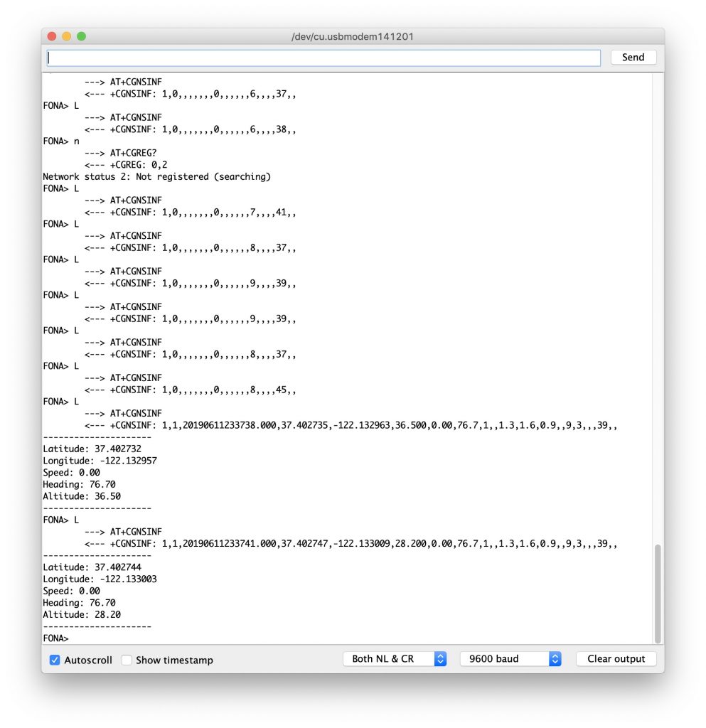
My first milestone was when I was able to get the shield to acquire GPS satellites and print out the longitude and latitude, and connect to a cellular network. First, I had to solder the pin headers onto the GPS shield. This took quite a while, and the soldering practice I got from MintyBoost proved to be very useful. Once I had finished soldering, I attached the shield to the Arduino using the headers. Then, I powered the Arduino/Shield combo by plugging in the USB cable to the Arduino and a 3.7V LiPo battery to the shield. I loaded the Arduino with example demo code, and opened the Serial Monitor (9600 baud). From there, I was able to see that the shield is properly responding to AT commands. I turned on the GPS module using the command AT+CGNSPWR=1. Then, I used the command AT+CGNSINF to print the current GPS location. I kept doing this until it was able to print GPS coordnates.
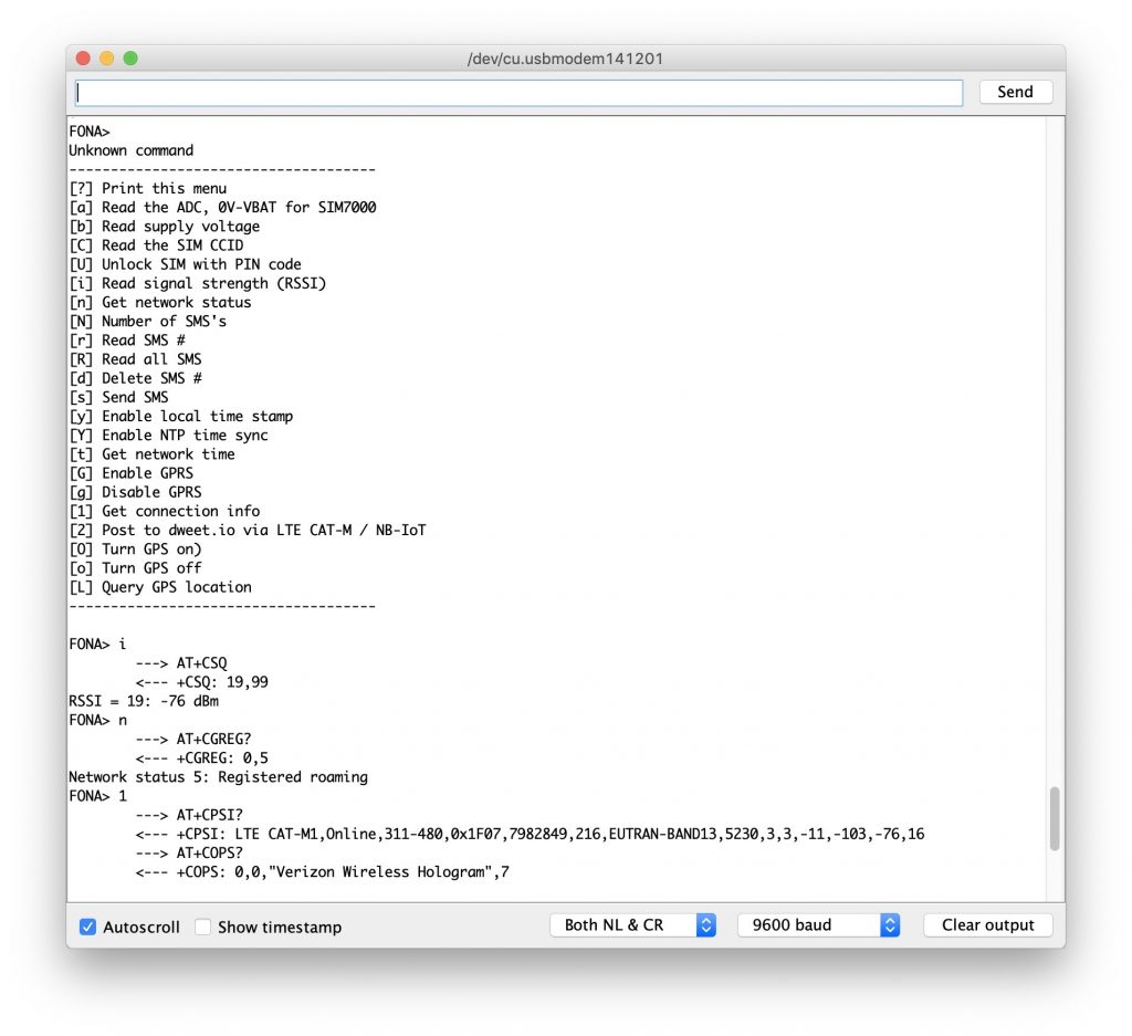
The next step was to get the shield to connect to a cellular network. Normally, when the shield is powered on, it is supposed to connect to a LTE-CAT M1 network on its own. But, the shield was not doing that. It kept saying “Searching”, and it would never connect to a network. After reading alot of documentation from the manufacturers page on GitHub, I tried forcing the shield to use LTE and LTE only. The shield has the ability to fall back to Edge or 2G if LTE is not available. After doing that, the shield was able to successfully connect to Verizon’s CAT-M1 network, which made me super happy.
MintyBoost
My starter project is the MintyBoost. The MintyBoost is a smaller portable USB charger that uses two AA batteries to power a USB device. I chose this starter project to learn and practice soldering and desoldering.
How it works: The board utilizes the LT1302 chip to boost the 3V from the AA batteries to 5V. The LT1302 chip on the board first sends power from the AA batteries to the capacitors and the power inductor, then releases the power from them to the USB device.
Learned: During the making of this project, I learned all about the different components in this build. I learned that resistors limit voltages, capacitors and power inductors store energy, and diodes only allow current to flow one way. I learned about to solder and unsolder parts to and from a PCB board.
Mistakes: I made plenty of mistakes during this project. I kept using too much solder, had trouble using the wick, and I even managed to solder the USB jack on the wrong side of the board. It took alot of energy to unsolder it from the board and put it back onto the right side of the board.