Final Blog:
Hi my name is Danielle and I am an up rising sophomore going to Promise Academy High School. For my starter project I built a Mini POV. It was fairly easy to build because it was a simple kit. To program and customize it was hard for me because I didn’t know anything about programing. I had to download the Arduino app off of their website. After I learned how to write code I decided not to program it because I was running out of time.
For my final project I was supposed to have made a 3x3x3 LED cube. Unfortunately I soldered my ATMEL microcontroller and 3X8 MUX chips on backwards causing the chips to get dangerously hot. While I was trying to save the chips I burned them and the board. So with the help of my lead instructor we decided to keep building the cube using an Ardunio UNO since I still had all my LEDs. After I discovered that with the Ardunio UNO I could have up to five sensors to add to my cube I decided to stack my LEDs.
Unfortunately, while I was doing this I shorted a few LEDs. I didn’t notice this until I plugged it in and certain LEDs weren’t lighting up as they should have. I also saw smoke which indicated that I burned two of my LEDs. So with this I decided to make the cube 2x2x1 as a proof of concept. I programed the cube to display a certain pattern that I created and programmed. I also created two other colors which were yellow and light blue. This was a plus because I was using RBG LEDs which lights up red, blue, and green.
During this program, even though my project didn’t turn out as planned, I learned how to write C code, how to build and debug my hardware and how to work past mistakes.
#1 Milestone: Blinking LED
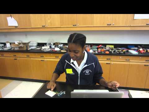
Hi my name is Danielle and I programed a RGB LED to blink in a specific order. To do this, I first had to create the blink code by using the Arduino software (http://Arduino.cc/en/Main/Software). In this code I specified how slow of a delay I wanted from the LED and what colors I wanted to show in a specific order (green, red, blue). To get the actual LED to blink I first had to put the LED and a resistor into a bread board. The bread board allows you to experiment with circuit design. I also connected each of the colors of the RGB LED on the bread board to the Arduino UNO using wires. This allows the Arduino to tell the LED what light to emit.
Below is some of the code that I used with comments as to what it means. Comments come after the “//” :
// Pin 12 has an LED connected on most Arduino boards.
// give it a name:blue, green
int led1= 8; //blue led
int led2= 9;//green led
int led3= 10;// pin10 corresponds with red led
// the setup routine runs once when you press reset:
void setup () {
// initialize the digital pin as an output.
pinMode(led1, OUTPUT);
pinMode(led2, OUTPUT);
pinMode(led3, OUTPUT);
Starter project: MiniPOV
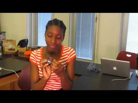
Hi my name is Danielle and for my starter project I worked on the MiniPOV 3. Like many starter projects, the MiniPOV came in a kit. This kit has everything that you need to make the MiniPOV. This includes:
- 8 red LEDs
- AA battery case with switch
- 3 4.3k resistors
- 8 100ohm resistors
- 3 5.6v zender diodes
- female computer port
- PCB
- ic1 micro-controller
- ic1*
The LEDs (light emitting diodes ) produce light so you could see a message. The resistors help channel current into the LEDs so that they don’t short circuit. The PCB is a board that you would be working on. The computer port is there to help you connect the MiniPOV to the computer so that you would be able to upload codes. The Ic1 micro-controller holds all the codes so that the LEDs would light up a specific way.