RC Tank
For my main project I’m building an RC tank. My main project requires a lot of coding and soldering. For some parts I followed a kit, but the most challenging were the parts like coding where it required integrating research from many places.
Engineer
Daniel
School
Ramaz
Grade
Incoming Junior
Final Milestone
#include <PS2X_lib.h> //for v1.6
PS2X ps2x; // create PS2 Controller Class
int EN1 = 9;
int IN1 = 4;
int IN2 = 5;
int IN3 = 6;
int IN4 = 7;
int ENB = 3;
int SPEED = 100;
//right now, the library does NOT support hot pluggable controllers, meaning
//you must always either restart your Arduino after you conect the controller,
//or call config_gamepad(pins) again after connecting the controller.
int error = 0;
byte type = 0;
byte vibrate = 0;
void setup() {
Serial.begin(57600);
pinMode(EN1, OUTPUT);
pinMode(IN1, OUTPUT);
pinMode(IN2, OUTPUT);
pinMode(IN3, OUTPUT);
pinMode(IN4, OUTPUT);
pinMode(ENB, OUTPUT);
//CHANGES for v1.6 HERE!!! **************PAY ATTENTION*************
error = ps2x.config_gamepad(13, 11, 10, 12, true, true); //setup pins and settings: GamePad(clock, command, attention, data, Pressures?, Rumble?) check for error
if (error == 0) {
Serial.println(“Found Controller, configured successful”);
Serial.println(“Try out all the buttons, X will vibrate the controller, faster as you press harder;”);
Serial.println(“holding L1 or R1 will print out the analog stick values.”);
Serial.println(“Go to www.billporter.info for updates and to report bugs.”);
}
else if (error == 1)
Serial.println(“No controller found, check wiring, see readme.txt to enable debug. visit www.billporter.info for troubleshooting tips”);
else if (error == 2)
Serial.println(“Controller found but not accepting commands. see readme.txt to enable debug. Visit www.billporter.info for troubleshooting tips”);
else if (error == 3)
Serial.println(“Controller refusing to enter Pressures mode, may not support it. “);
//Serial.print(ps2x.Analog(1), HEX);
type = ps2x.readType();
switch (type) {
case 0:
Serial.println(“Unknown Controller type”);
break;
case 1:
Serial.println(“DualShock Controller Found”);
break;
case 2:
Serial.println(“GuitarHero Controller Found”);
break;
}
}
void loop() {
ps2x.read_gamepad(false, vibrate); //read controller and set large motor to spin at ‘vibrate’ speed
delay(20);
int right_y = map(ps2x.Analog(PSS_RY), 0, 255, -255, 255);
int left_y = map(ps2x.Analog(PSS_LY), 0, 255, -255, 255);
Serial.println(right_y);
Serial.println(left_y);
analogWrite(EN1, abs(right_y));
analogWrite(ENB, abs(left_y));
if (right_y < 0) {
digitalWrite(IN1, HIGH);
digitalWrite(IN2, LOW);
Serial.println(“forward Right”);
}
else {
digitalWrite(IN1, LOW);
digitalWrite(IN2, HIGH);
Serial.println(“Backwards Right”);
}
if (left_y > 0) {
digitalWrite(IN3, HIGH);
digitalWrite(IN4, LOW);
Serial.println(“forward Right”);
}
else {
digitalWrite(IN3, LOW);
digitalWrite(IN4, HIGH);
Serial.println(“Backwards Right”);
}
}

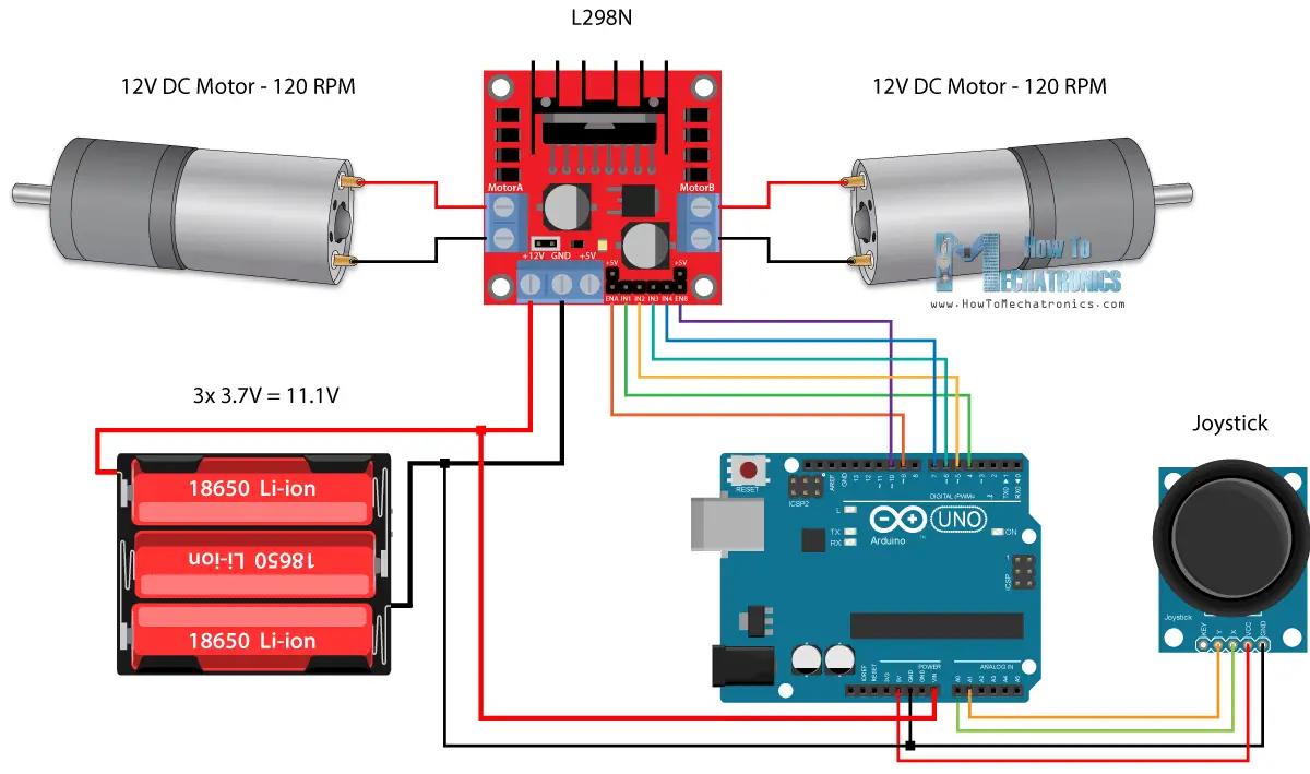
Schematic of ps2x connected to the Arduino uno, and Arduino uno connected to the motor driver.
Starter Project
