Hi, my name is Cindy and I am a rising junior at KIPP Houston High School. I began my first two days of this program with my starter project called the Drawdio Starter Kit which is a project where you can create a pencil that produces sounds when written with. I chose to start off with this project because I was curious to see how it would turn out in the end and it also sounded like a fun object have to play around with. However my main project was the RGB LED light display which is basically a design on plexi glass that can be lit up and change colors by using RGB LEDs. By starting off with no experience with engineering at all, it was very confusing, but as time passes you learn along the way making it less difficult to overcome challenges.
Final Project: RGB LED Light Display


Cindy’s BOM
Schematic for my Light Display

Procedure for creating this artistic project
1. Read throughout the RGB LED Love Heart instructable to get familiar with what materials are needed and what is needed to be done in each step.
http://www.instructables.com/id/RGB-LED-Love-Heart/
2. Create a Bill of Materials to organize all the information about each individual part that is needed to complete the project
3. When you are provided with all the materials needed, then learn and search up specifically about all the electrical components that are going to be used such as the RGB LEDs, NPN transistors, and resistors.
4. Test to see if the LEDs actually function, then you will need to test all of the components on a breadboard which does not require any soldering and is used mainly for temporary circuits.
5. For first users of the breadboard, be sure to seek information on how to use it and how it functions so that there is no confusion. By obtaining this knowledge, then you can successfully connect everything to one another using jumper wires and seeing whether or not you will need to make some changes in the components that you are using based on how the LED looks when lit up.
6. To give it power, you will need to connect a jumper wire from the breadboard to your desired voltage on the Arduino and download the Arduino program. By doing this I got to test it with the blink code and with this, it actually tells the Arduino what pattern of colors the LED should turn to.
7. After you have lit up one of the LEDs, then you can incorporate what you have just learned to be able to connect all the other LEDs as well so that you don’t just have one.
8. Once all the LEDs have been tested, then you can start working on the acrylic part of the project. First you would need to draw where the holes of the LEDs would be on the bottom of the plexi glass and make sure to measure them within equal distances of each other or the LEDs won’t fit like they should. You would also need to measure half an inch from the bottom of the plexi glass and draw a line across to the other side so that you know where to stop when drilling.
9. Once everything has been measured out, then you can start drilling into the holes. First start off by making a starting point which is where you would take a small drill bit and hammer it into the spot where the LED will be so that when you increase the size of the drill bit it won’t slip off to the side.
10. You would then start from a small drill bit and work your way on up until you get to the 1/8′ inch drill bit which should make the hole big enough for the LED to fit through. Do this for the rest of the holes as well. When all the drilling has been done then you can place a strip of aluminum tape across the top so that the light can reflect across it making it as bright as possible.
11. To create the design onto the glass, you first must choose whichever design you desire and print out a copy of it. Tape this across the top so that it can stay in place and while using an exacto blade, you can trace out the all the lines that the design is composed of very hard so that the line actually shows up on the glass. When you are done with this, then with sandpaper, you can shade in the inside of the design except in the direction that the shape is going so that it all looks different from one another.
12. Now that the plexi glass is complete, you can start soldering on what you did on the breadboard onto the perfboard that is provided. Be sure that everything is in the correct spot because it is more permanent than the breadboard and make sure that there are no loose wires. When everything is placed together, you can place electrical tape onto the bottom where all the wires are at so that it takes away all the attention from the rest of the project.
13. To keep the Arduino hidden from the viewers, you can actually place it into its a box but it should still allow the wires to come out of it since that is where the LEDs are getting their power from.
14. Lastly when everything is accomplished, you can now test it out to see if it works and if it’ll be able to stand up by itself. If not, then you can make a stand for it in the back to keep it from falling over.
RGB LED’s Arduino Code
Here is my code that I used to download into my arduino and control the light patterns of the RGB LEDs.
Cindy_s_RGB_LED_Light_Display_Code
Final Project- Final Milestone Video

In this milestone, I achieved this accomplishment by completing the electric circuit within the 7 RGB LEDs that were soldered onto the perfboard and the acrylic design of the plexiglass as well. I got everything connected to the perfboard by transfering everything that I had done and learned previously from the breadboard that I used at first to test out a few of the LEDs. In order for all of the seven LEDs to be aligned adjacent to one another with equal distances between each one, I had to cut the perfboard in half and place them next each other to make it longer. Once I had all of the LEDs, transistors, and resistors in place, I then had to connect the right pins to the correct components; however this process took a while to complete since the wires either kept breaking, there were loose wires, or made incomplete connections causing the LED to not show all of the colors or sometimes not even light up at all. Afterwards, to have the Arduino connected to everything but at the same time not making it visible for the viewers to see, I included a box on the back of the display to put the Arduino to make it appear professional and neat.
Furthermore, I then started working on the design of the plexi glass by first measuring out and drilling where the LEDs were going to be placed on the bottom of the glass being sure to not drill in the wrong spot. On the top side of it, I traced out all of the lines of the design with an exacto knife in a way where it shows clearly on the glass and in between them, I used sandpaper to let the audience tell apart the shapes so that they do not all look the same. Lastly, on both sides of the bottom of the glass, I placed a strip of aluminum tape so that the light can reflect off of it making it as bright as possible. Once I had accomplished all of this, I really enjoyed how it turned out because it exceeded my expectations.
RGB LED Light Display- First Milestone Video
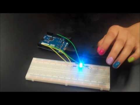
For my first milestone, I achieved the accomplishment of testing out one RGB LED to see if it will produce a variety of colors and in which it did. To do this, I first had to familiarize myself of how the breadboard actually functions so that I would be able to connect everything properly. At first, it seemed so confusing since there is an abundance of holes all over the breadboard but once obtaining the knowledge of what everything is, then it really does not seem so difficult. On both sides of the breadboard, there are two rails that can be used for power, the outer one is known as the negative rail while the inner one is the positive rail. However, the two thick columns of holes on the side of the power rails are powered differently. Instead of just placing a wire anywhere, you actually need to place the wire into the right row since all 5 holes in one row going horizontally are all connected to one another. Afterwards, I needed to be informed more in depth about the RGB LED and the significance of each pin. In total, there are 4 pins, although there is one pin that is much longer the rest while the others are similar in length. If the LED was on the side where the longest pin was on the inner most left, then the first pin would be the red one, then the power leg which is also known as the common anode, followed by the green pin, and lastly the blue pin. Furthermore, I discovered a website that could guide me to lighting up the RGB LED. I first placed the LED with the power leg on F42 with the red pin next to it in F43. Since the longest pin is the power pin to the whole LED, there should be a jumper wire connected in any hole in the same row as the common anode to the 5 volts pin on the Arduino. Now I can start connecting in the resistors by first connecting one end of the 150R in the same row as the red pin while the other end of the resistor should be connected by a jumper wire to the PWM pin 6. Once I accomplished this, then I started plugging in the other resistors by placing one end of a 91R in the same row as the green pin and connecting the other end a few holes away from it. Then I placed a jumper wire in the same row as the other end of the 91R to the PWM pin 3. Lastly, I placed one end of the last 91R in the same row as the blue pin which placing the other end of it a few holes to the side of it. In the same row, I placed a jumper connecting at PWM pin 5. Once I completed all of these multiple steps, I then programmed my Arduino using the code that the website provided for me which eventually allowed the RGB LED to glow in a variety of colors. In conclusion, when everything is connected to one another, the circuit will be completed and the RGB LED will be able to glow, mixing the three colors along the way to create new ones as well.

Reflection
Spending about half of my summer vacation here at BlueStamp was definitely worth my time by it being a once in a lifetime experience. I have obtained an excessive amount of knowledge that I know I would not have been able to receive anywhere else even at my school. When I first came, I arrived not knowing a single thing about engineering or even the thought of pursuing the dream of becoming an engineer. However, all of that has changed over the past 6 weeks by experiencing the challenging obstacles they must face in order to reach their goals and meeting different types of engineers as well. After I had accomplished completing my main project, it really surprised me in a way because it became more than what I had expected it to be causing me to realize how I could branch off of this project with newer ideas to create something more advanced and complex. Although, throughout my experience, I would not have been able to achieve my accomplishments without the help of my instructors and peers. They have also been a big part of the program because they all have helped me overcome my challenges and made the program much more enjoyable as well. Overall, I am grateful to have attended the BlueStamp Engineering Program because I know that it will help me succeed later on in the future in school or even in the real world.
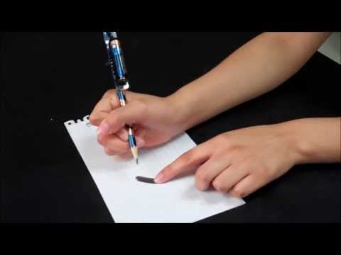
The Drawdio Starter Project
The Drawdio Starter project is a kit where a person can create a pencil that can produce music as it writes. It is an enjoyable tool that many can use to experiment around with when drawing or writing and they can also learn all about how the tool actually functions by the parts that it contains. Connected onto the pencil is a circuit board which is composed of the battery holder,speaker,and much more individual parts while there is a copper strip wrapped around the bottom of the pencil then soldered onto the end of the circuit board. Obviously since the triple A battery is the power supply for the whole invention, that is where the power emerges from which keeps everything running. Although, the main heart of the gadget is the TLC551 chip which can run as low as 1 volt. Additionally, it also creates audio-frequency oscillations but it is not entirely powerful enough to play on speakers. Once the chip feeds current into the capacitor which is an electrical component that stores electrical energy, when it’s full, it then slowly drains out. The size of the capacitor helps regulate how long it takes it to fill in the beginning. To do both tasks, there are these 2 resistors called RB and RA that determine how fast to fill and drain the capacitors. Nevertheless, there are also two types of transistors used which are the NPN and PNP transistors that are used to perform the function of a switch or amplifier. Each of the transistors both include three terminals called the collector, the base, and the emitter to help the current flow into and out of it. With all of these electrical components attached to the circuit board, then the whole circuit will be able to work causing the device to produce noises. Furthermore, there were some trouble spots that occurred in the process of creating this invention such as at first there was a mix up in the instructions since on the website there was an updated version when we were actually suppose to use the older version. Simultaneously, once everything was completed, I had trouble testing to see if it could produce noise because at first, I did not know that you had to also touch the graphite and write at the same time. The reason being is that your body acts as a sensor when touching the graphite completing the electric circuit. However, you can improve the conductivity by placing a penny in between your finger and the graphite. Down below shows the actual device and all about it as well.