Intelligent Door Lock
This Intelligent Door Lock is capable of using Amazon’s Rekognition technology and takes pictures of people waiting at a door, recognizes features of those people, and can open or close a 3D-printed lock depending on the user’s preferences.
Engineer
Christopher P
Area of Interest
Physics, Mechanical and Electrical Engineering
School
Regis High School
Grade
Incoming Junior
Reflection
Before becoming a part of the BlueStamp program, my experience with engineering was limited to building and coding competitive robots. After completing the program, I’ve been introduced to all kinds of electrical and mechanical components that I would love to explore in future projects. From day one I learned how to use a soldering iron, a tool I had never even seen before. I learned how to set up and use a Raspberry Pi by the second week which has limitless possibilities for future projects. I learned how to code in Python, a coding language I had never seen before. Being part of BlueStamp also taught me the importance of hard work and the right time to hustle. Being part of “Team Awesome,” as we called it, was a fantastic morale booster and gave me a huge motivation to finish my project. I’m glad I was opened up to new areas of engineering which I look forward to exploring further.
Final Milestone
- SetAngle(angle) – sets what angle the servo should turn to when opening and closing the door.
- CloseDoor() – Turns the micro servo to the 90 degree position to lock the lock.
- OpenDoor() – Turns the micro servo to the 0 degrees position and unlocks the lock.
- Capture() – Opens the camera’s preview, takes a picture, saves it as Chris.jpg in the photos folder, and closes the preview.
- Send_email() – Accesses a fake email account I made called [email protected] and sends an email with the picture to my personal email account.
- Get_client() – Accesses the Amazon Rekognition software
- Get_args() – Accesses the arguments of collection and image so I can input the specific image and collection I want the code to check.
- Check_face(client, file) – Checks the picture that was just taken to see if there was a face or not.
- Check_matches(client, file, collection) – If check_face() is true, the code will go into the specified Amazon Rekognition collection and compare the picture it just took to everything in the collection.
- Facematch() – Matches a picture with one in the collection. It will only work if there is a face that is at least 85% similar to one in the collection.
The boolean variable “lock” is still in effect for this code. The code uses those true and false values to determine which functions to run. It will either open the door or close it. If the button is pressed and the variable is true, the camera will take a picture and send it to me via a fake email account called [email protected]. It saves the picture as Chris.jpg and runs facematch.py on it using the facematch() function. If it matches a picture I have uploaded to the bucket, the lock will open. If not, it will stay locked. Once the door unlocks with the OpenDoor() function, the variable “lock” is set to true like in the last milestone. Pressing the button again will lock the door.
Finishing this project is truly incredible to me. I essentially designed a home security system using a Raspberry Pi, Python code, and a 3-D printed lock. There are countless possible modifications to be made such as adding a fingerprint scanner and a keypad. This project is, at it’s core, completed, but there’s always more to do.
Third Milestone
I used 3D-printed parts from a design I found on Thingiverse.com. https://www.thingiverse.com/thing:465349
I used metal wire to attach the micro servo to the container part and then screwed the container to the base. I then but the gear onto the micro servo which fits comfortably. Then I did some research on the Raspberry Pi’s GPIO pins, specifically how to connect them with jumper cables to send a signal to the servo. Here’s the result of using the code “pinout” on the Linux Terminal.
This is how I was able to know which pins were the right ones. Here’s the jumper cable setup on my Raspberry Pi.
First a cable had to be connected from a GPIO pin (I chose GPIO 2). The cable runs to a breadboard pinhole and sends a signal to a button. Another cable runs from the button back to a Ground pin on the Raspberry Pi. Then, 3 cables are connected between the Raspberry Pi to the micro servo. There are 3 different colored wires on the micro servo: Brown, Red, and Orange. The Brown wire connects to another Ground pin on the Raspberry Pi. The Red wire connects to a 5V pin that sends power to the servo. The orange wire connects to another GPIO pin (I chose GPIO27) and sends a signal to the servo to open and close the lock. The micro servo works by moving its angle to a certain position when I want to open and close the lock. Here’s a description of the code I used.
This function allows me to change the angle of the servo’s gears. Here’s the OpenDoor() function:
It sets the angle of the servo to 0. Here’s the CloseDoor() function:
Similarly, to the open door function, it sets the angle to 90 to close the door. To get these functions to work at the right time, I created a global Boolean variable called “lock.” Boolean means that the value is either true or false. When it’s true and someone hits the button, the door is locked and the code goes through its process of taking the picture and choosing whether to unlock the door or keep it locked. At the end of the code, lock becomes false. When the button is pressed and lock is false, the Raspberry Pi just sends a signal to the servo to lock the door. Here is how the code runs:
When I press the button, the Linux Terminal prints the words “Unlocking” and then the lock unlocks or prints “Locking” and the lock locks.
Getting to this point is super cool for me. I’m really proud of all the work I’ve done so far. The biggest struggle of this milestone was definitely putting the lock together. Moving the big gear wouldn’t move the gears inside of the servo. It turns out the screws in the 3D-printed door-lock were just too tight. At this point I have used the camera and recognized my face and now I’ve opened and closed the lock. Now I have to combine it all into one code and I’ll have a functioning intelligent door lock.
Second Milestone
I reached my second milestone: image recognition of my own face. I took a picture using the Amazon Rekognition database to recognize a picture of myself when compared to other pictures in the database. Amazon Rekognition is an image analysis service, part of Amazon Web Services (AWS). AWS is a subsidiary of Amazon.com with all kinds of uses like storing information and facial recognition. To accomplish this, first I needed to create an account with AWS. I then used the following Terminal code in the Raspberry Pi Linux Terminal which enabled me to control certain AWS functions from the Terminal.
Next I cloned a GitHub repository (https://github.com/af001/pi-detector.git). When I put the code into Terminal, it installed a folder with Python code useful for facial recognition. I used the following Terminal code to create a collection on Amazon Rekognition called “home”.
Collections store photos to compare with unrecognized pictures. I repeated this code: “python ../scripts/add_image.py -i ‘image.jpg’ -c ‘home’ -l ‘Chris’” (changing the picture in image.jpg each time) to add multiple pictures of myself to the home collection and associate them with the name Chris. I used a Python code like the one displayed in my First Milestone to take a picture of myself and save it as Chris.jpg. I then ran the Terminal code: “python facematch.py -i ‘Chris.jpg’ -c ‘home’” which ran the code facematch.py. It compared Chris.jpg to all the pictures in the home collection and the results came back saying the face in Chris.jpg was 98.9% similar to pictures associated with my name, recognizing my face.

Results of running facematch.py on Chris.jpg
Here’s a description of how facematch.py works.
The function get_args() sets up the arguments for the image and the collection so the code can compare an image to all of the others in a specific collection.
The function check_face(client, file) detects if a specified image contains a face and if it does it continues on with the code.
The function check_matches(client, file, collection) checks a specified collection of images for all faces that are at least 85% similar.
The function main() prints the results of the search. If a face is detected, it prints out the name associated with the face and how similar the faces are to each other. If there are no matches, it prints “No faces detected”
Now the project is starting to really take shape. The camera now takes pictures and recognizes my face. The hardest part of this was setting up the Amazon Web Services account. It was long and complicated process and the website itself is difficult to navigate, especially when the Raspberry Pi’s internet connection is slow. All in all though this project is really cool so far and soon I’ll be able to open and close the door lock.
First Milestone
A Raspberry Pi
A power supply
A Micro SD card
A USB keyboard
A USB mouse
A Micro SD card reader
A Monitor with HDMI ports
An HDMI cable
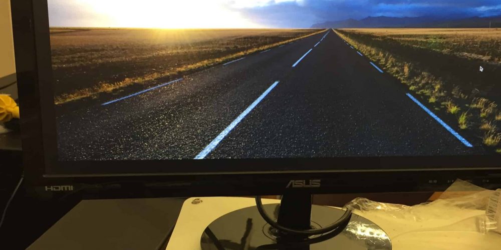
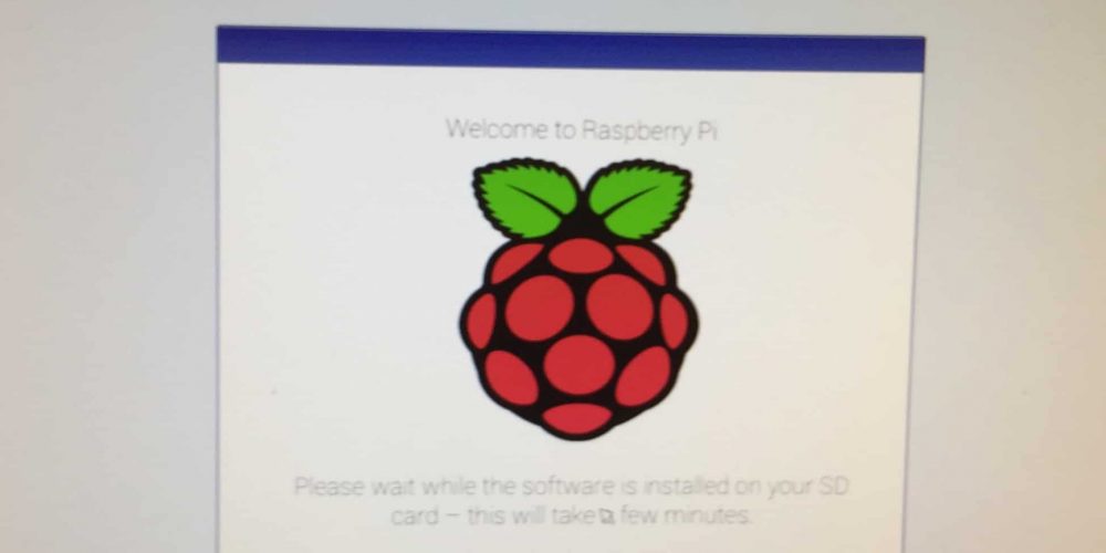
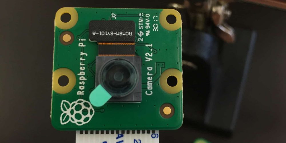
First, I installed NOOBS to the Raspberry Pi’s Micro SD card. NOOBS is a zip file that includes software for setting up Raspberry Pi, including the Raspbian operating system. I plugged a monitor, keyboard, and mouse into the Raspberry Pi, creating a mini-computer with about 1 GB of data storage. Once I installed the Raspbian Operating System, I opened up the Terminal and installed Python with the code: “Sudo apt-get install python-serial”. Terminal is a window which allows users to input commands that directly manipulate their Raspberry Pi’s system. https://www.raspberrypi.org/documentation/usage/terminal/. Python is one of various coding languages that can interact with the Raspberry Pi. Most code for the camera and the Pi itself comes from Python files. Having the prefix “sudo” which stands for “super user do” gives the code certain elevated privileges to perform certain administrative tasks such as listing the objects in a file and shutting down the system. https://www.computerhope.com/unix/sudo.htm. I used the website codeacademy.com to learn the basics of Python. Using codeacademy.com, I learned how to print out words based on specific criteria and even how to write my own Mad Libs. I plugged in the Raspberry Pi’s camera module and researched how to set it up. I enabled the camera’s software inside of the system’s preferences. Then I opened up a new Python file and typed in this code:
This code calls the camera’s start_preview function and delays the camera using the sleep function for 10 seconds, and then calls the stop_preview function to close the window. The monitor displays everything the camera sees for those 10 seconds. “From picamera import PiCamera” is necessary code for every time the camera module is being used. It takes a class called PiCamera (capitalized) from a library called picamera (not capitalized). A library is a collection of code. A class is used to create an object and gives an object its variables and functions. https://www.learnpython.org/en/Classes_and_Objects. In this case, PiCamera() is a new object associated with the variable “camera” which allows you to open and close this preview on the monitor. Then I inputted the following Python code into a new Python file:
Like the last code, this one opens up the preview on the monitor. After 5 seconds, it takes a picture and then closes the preview. The picture is saved as “image.jpg” which is saved to the desktop folder inside of the Pi folder. Eventually, the camera module successfully takes pictures which will later be stored on Amazon and each face’s features will be recognized using the Amazon Rekognition software.
Picture 1: Raspberry Pi computer with monitor, keyboard, and mouse
Picture 2: Installing Raspbian
Picture 3: Raspberry Pi Camera Module
MiniPOV
For my starter project, I built a MiniPOV4 (Mini Persistence of Vision) device that creates a pattern or image when waved quickly through the air. It creates this pattern through the specific and accurate timing of LED lights, light emitting diodes. A diode is an electrical component that only allows current to flow in one direction. To allow this device to work, all of its major components had to be soldered on individually.
The MiniPOV requires 10 different soldered parts:
- USB-jack
- Microcontroller
- LED lights
- Zener Diodes
- Resistors
- Capacitors (ceramic and electrolytic)
- Transistors
- Potentiometer
- 12 MHz Crystal
- Battery Pack
To display the pictures and patterns, images are downloaded from a computer to the MiniPOV4’s USB-jack. The 28-pin microcontroller in the center is the brain of the device. It interprets the images from the USB-jack and creates a timing for the LED lights. Two different types of resistors, 2.2k ohm and 47 ohm, regulate the electrical current sent to the LEDs so that they don’t overload. Zener diodes, like the LEDs, must be placed in a specific direction to send current in one direction. These specific diodes stabilize the voltage sent to the USB-jack. The device uses two different types of capacitors, ceramic and electrolytic. Capacitors, unlike resistors, help store energy for the device. These specific capacitors help balance the input and output voltages. The device’s three transistors control the Red, Green, and Blue colors of the LEDs. They provide enough current to power the 8 LEDs. The big blue box is the potentiometer. It translates rotation into resistance or, in other words, causes the LED flashes to speed up or slow down. The 12 MHz crystal is similar to a crystal in a watch. It keeps the LEDs flashing at a consistent speed. Finally, there’s the battery pack, which had its wires cut, stripped, and soldered onto the board. It provides power to the MiniPOV4 with three AAA batteries.
This project was fun overall, but was not without its share of difficulties. It was my first experience with a soldering iron which led to the occasional need to desolder parts with too much solder or which were not placed correctly. In the end, only two LEDs did not work. Every other part did its job correctly. Since humans can only move their arms so fast, it’s a little difficult to see the image in the MiniPOV4, but the colors are all there and timed as they should be. Upon completing this project, I learned how to solder parts to a circuit board, how soldering different parts connects them into a whole system. It was a great beginning to my STEM summer camp experience!


