Hello, my name is Chase. I am a rising junior at Staten Island Technical High school. My main project is the Third Eye for the Visually Impaired/Blind which uses an ultrasonic sensor to give live feedback for respective distances.
Engineer
Chase T.
Area of Interest
Biotechnical Engineering
School
Staten Island Technical High School
Grade
Incoming Junior
Reflection
In my future, I want to go into biotechnology. I have a passion for the medical field as well as technology. That’s why bluestamp was such a great experience for me.I have been to several medical summer programs, as well as volunteering at the hospital on weekends; however, when it comes to engineering, I do not have much experience. This really opened my eyes to new horizons. It gave me abilities that I would otherwise have never explored. For instance, who would have known I was going to spend hours upon hours learning how to sew? I ended up sewing together several hand wraps and components to assemble, both, model 1 and 2 of the third eye for the blind As Bluestamp comes to an end, however, I cannot help but look back and see how much I have grown, not only knowledge wise, but as a person. This program has made me a better student, worker, and definitely pushed the limits of commitment. So, once again, I am Chase and this is my project. Thank you.
Final Milestone
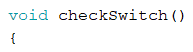
For my final milestone, I configured and tested new sensors to add to my “Third Eye.” After assembling the second module and making sure all individual parts work correctly, the only thing left is to code and integrate every part within each other. I need to implement the flex sensors, as well as the improved switch functions, with the vibrating motor and the buzzer, in order to make this project more user friendly. began the code for the flex sensors by creating a “checkswitch()” function.
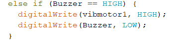
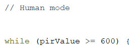
This else statement states the opposite as the if: if the buzzer is on, turn that off and turn the vibrating motor on. The goal for this function is to enable the “Third Eye” to instantaneously switch between the vibrating motor and buzzer at any time — replacing the need for a switch. In addition, I need to perfect the infrared sensor code, and integrate that into the normal Third Eye code to make it as effective and interactive as possible. Another goal is to make it more sturdy, as well as neat. User friendliness is a key part to a machine like this, especially when it is designed for visually handicapped people. I began the PIR sensor code with a while loop named “Human Mode.”
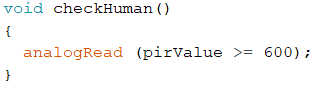
To break out of the while loop I wrote a “checkHuman()” function that I simply put at the end of the code and it reads thee analog values from the PIR sensor to remind the while loop to check if there is still a human in front of it.
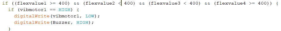
The next step for this code is the logic. Using “if, else” statements, I came up with this.
The logic for this code states that if the sensor value for your pointer and pinky fingers are greater than or equal to 400, as well as, your middle and ring fingers are less than 400, then move on consecutively to a second if statement. This statement states that if the standard vibrating motor is on, turn it off and turn the buzzer on. I then added an else statement.
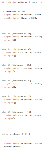
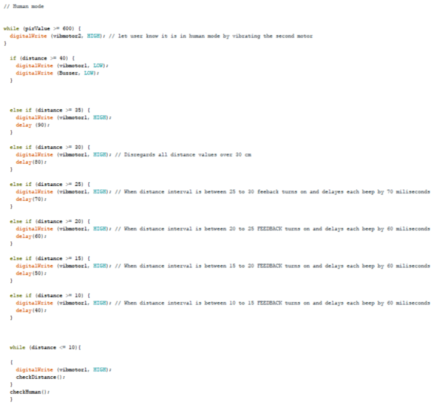
The second part to this code was adding the logic. While the pirValue is greater than or equal to 600 (my threshold), then turn the second vibrating motor on in order to let the user know there is human motion in front of them. As the second vibrating motor is running, proceed to run the normal distance code.
Overall, the code can and still needs to be improved. In the future, I can add more specifics to the values that maintain the flex sensors as well as the PIR sensor. For now though, I feel this project turned out well. There are many problems that still need to be resolved, but problems are always expected. Using the skills I learned here after these six weeks I can solve these problems in the future and feel ready to bring this project to its full potential.
Bill of Materials
Third Milestone
After completing the Third Eye for the Blind, my third milestone was customizations. After spending some time thinking about what to add to this module , I came up with the idea of using an infrared sensor to identify human presence. The idea behind this was to make the experience of my “Third Eye” more interactive for the user. Most people who are visually impaired or blind have trouble with making normal human connections that are essential to not only relationships but even everyday conversation. Something as small and simple as eye contact is impossible. However, with this additional aspect to the Third Eye, it could enable the user to have a closer connection to the person in front of them, for not only would you be able to tell where they are, but how far away.
As for customizations, one sensor was not enough. The second concept I had was adding flex sensors. Flex sensors are variable resistors that, when bent, are able to interpret finger movements from the change in voltage. I used the following tutorial to set up flex sensors:
https://learn.sparkfun.com/tutorials/flex-sensor-hookup-guide
The goal was to attach these flex sensors to the second version of the module. The second mole is actually a glove.There would be a function that turns a specific set of finger movements into a “switch” between the vibrating motor and buzzer. The next step was to put these concepts into a reality.
I began by doing research for the perfect glove: something lightweight but sturdy, comfortable but not too hot, and soft but not lacking grip. The goal was to have a glove that is able to be worn in any temperature without losing comfort. If it is warm out, you don’t want to be too hot in the glove; if it is cold out, you want to be able to stay warm; if it is room temperature, you want to, both, be not too hot but not too cold.
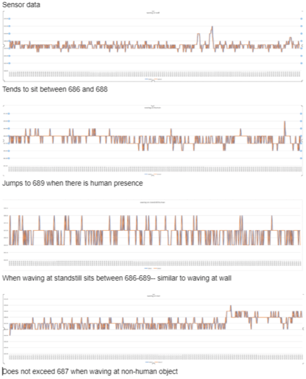
The next step was to find a solid infrared sensor that can do exactly what I want. I came across a PIR (passive infrared) sensor that detects human motion by analyzing changes in infrared radiation. The goal with this was to use this data to give the user the ability to identify the difference between an inanimate object versus a human in front of them. I attached this sensor into a breadboard and began running tests. I read the sensor originally through a digital pin, which uses 0 or 1 to say if there was human motion or no human motion. The problem, however, I was having was that the sensor read “high” all the time, meaning it always assumed there was human presence in front of it. The solution was to switch the input values into an analog pin. Using this analog pin I can now read values from 0-1023 versus 0-1. This higher resolution now allows me to analyze data to determine what a “human” looks like. After realizing this, I began running specific tests with the sensor; such as potential differences in infrared radiation when looking at an inanimate object while stationary or moving, as well as potential differences in infrared radiation while in the presence of a human stationary or moving. I connected excel with my arduino serial port and ran these graphs so I can visually see the live analog feed from the PIR sensor.
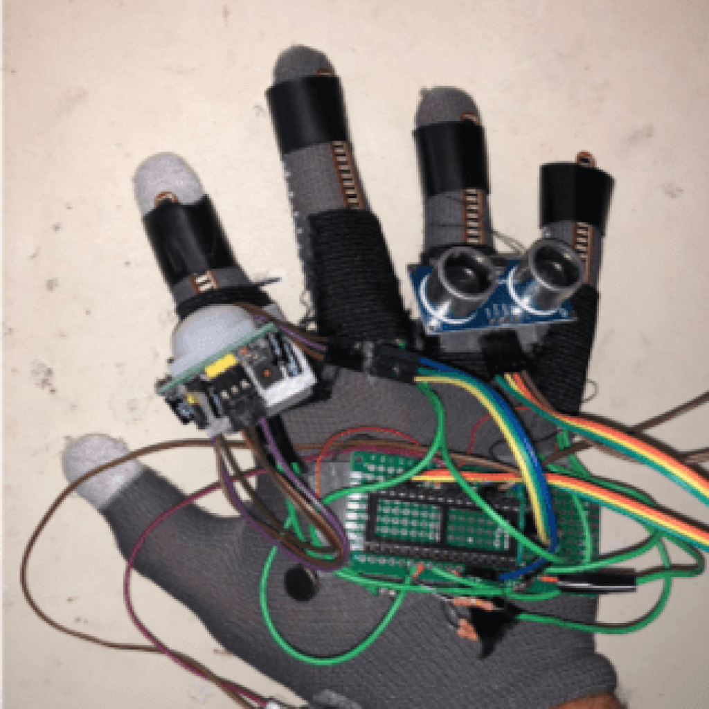
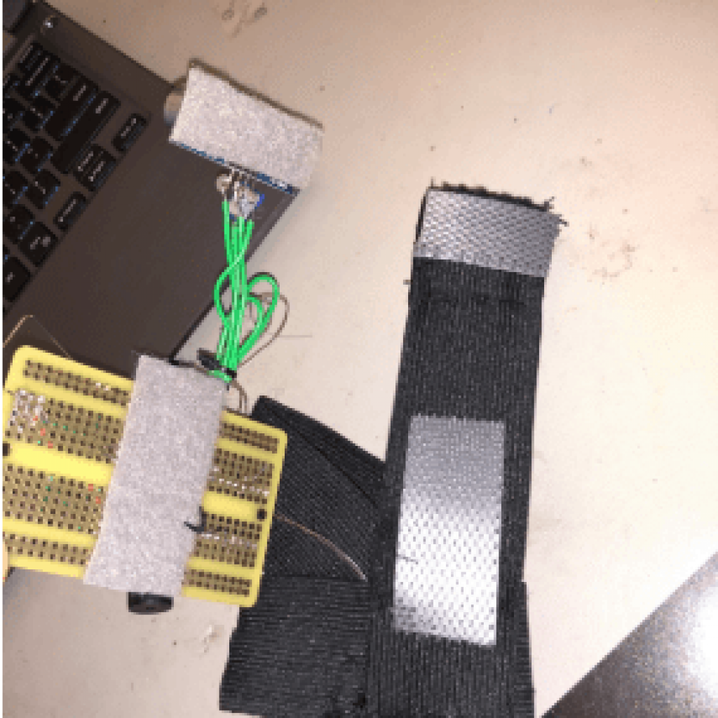
After finishing the implementation of the flex sensors, next was the infrared sensor. Which I soldered the same way I had it when connected in the breadboard. The last step was putting it all together. I used the Velcro that I used from my first module and attached everything onto the glove. The building of my second module was complete.
Now that I have tested and verified all the different components for the next version of my module, the next step is the integration of each into the entire system.
Within this milestone I really explored my abilities when analyzing data. Not only did I learn how to read data and cross reference it with other sources of information, but I also learned how to integrate excel with Arduino which can help me for future projects.
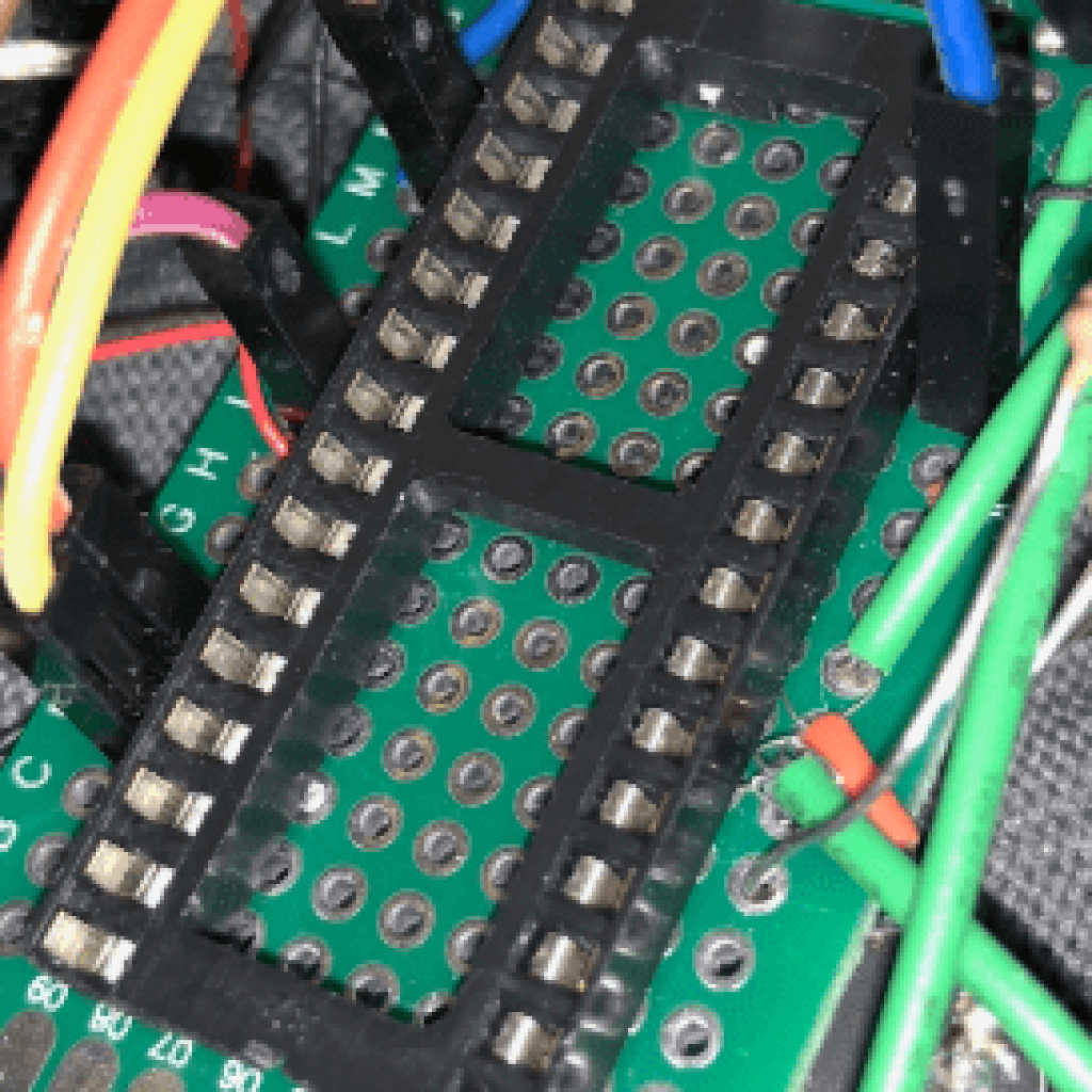
After finding the perfect glove, I had to start soldering. I first soldered an IC socket to the perfboard, so I was able to take the Arduino in and out as I wished. Then came soldering together the same components as module 1, which ensures that the project does not change, simply innovated
I visually saw a threshold that would enable my to distinguish the differences between simply motion versus human presence (because both detect “motion”). I implemented this threshold into my code and developed a “human mode” to the module.
Lastly came the flex sensor. Originally, I sewed the flex sensors onto each individual finger on the glove. The problem I came across with this was that since the sensors are smaller than the normal, they kept slipping out of the sew, as well as disconnecting at the soldered joints. To fix this, I used electrical tape to keep the flex sensor in place, however, I used the elastic wrap I have to keep the sensor down while enabling movement so It did not break from the seal. I then soldered all of this to the perfboard and it was then complete. After finishing the implementation of the flex sensors, next was the infrared sensor. Which I soldered the same way I had it when connected in the breadboard. The last step was putting it all together. I used the velcro that I used from my first module and attached everything onto the glove. The building of my second module was complete.
Second Milestone
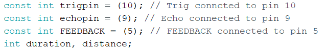
I began the code with a “const int” command, where I assign variable names to be later used for specific pins on the Arduino. The trigpin is designated to pin D10, the echopin is designated to D9, and the vibrating motor/buzzer are designated to D5, where D10, D9 and D5 correspond to digital pins on the Arduino. The second set of “int’s” are the duration and distance, which will be used later on and specifically mentioned in other blocks of code. Notice how they are not “const” (which stands for constant) because the values will change.
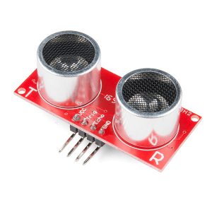
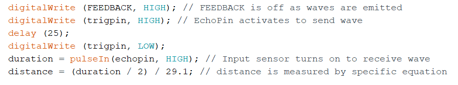
The second void command is “loop”. The “void loop” is defined as a loop that will continuously run your program as designed. For the Third Eye, the loop command begins with running the ultrasonic sensor. An ultrasonic sensor uses ultrasonic waves to measure the distance between it and the solid object in front of it. An electrical waves is outputted which then bounces off the object and back into the sensor. The sensor then takes this data and inputs it into an algorithm which calculates the distance of the object.
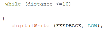
The next portion of code I struggled with greatly. The goal was to have the feedback have a pulse of 0 and simply vibrate or beep constantly when the distance is under 10 cm. Originally I assumed that I can follow the same pattern of code and simply make the delay 0. This led to a single beep/vibration rather than a constant feedback, which is not what I wanted. I did some research on my problem and came across a while function, which uses the same conditional statement as the “if” statement, but instead of performing the task in a loop, it is performed constantly whenever that condition is met. When using this function, it made the feedback perform exactly how I wanted it to, where when the distance is less than 10 cm give a constant feedback rather than a pulse.
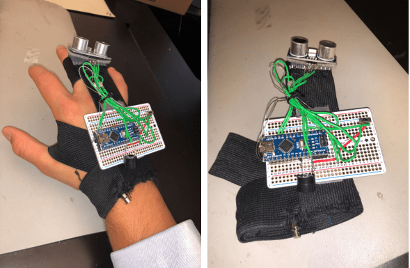
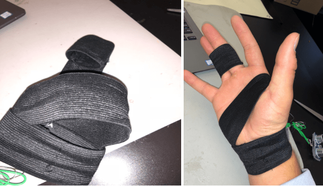
After completing the code, the next step was building the module. This step was rather simple considering I already assembled the module on a breadboard, so all I had to do was sew together a hand wrap, solder the components together, and place it on the hand wrap. I learned how to sew and began by making a bracelet type wrap that circumnavigates your wrist. I am now a seamstress.From there, I sewed a second piece of elastic to the “bracelet” portion, which wraps around your thumb for more support. The last piece of the hand wrap was the portion that holds the ultrasonic sensor.For this I sewed together a portion of the elastic that is held tightly around the middle and ring finger, and then attached that to the “bracelet”. The hand wrap is complete.
The last step to this process was placing the perfboard module on the hand wrap. I decided to use velcro to attach all of the necessary components. That way it is easily customizable and user friendly. I put velcro on the ultrasonic sensor was well as the physical perfboard and it stuck nicely to the hand wrap. As for the vibrating motor, since my original motor had broke, I had to switch to a different type of motor which could not be physically touched or else it would interfere with the pulses. My solution to this problem was to sew together a pocket for the motor that fit nicely in the hand wrap and was elevated enough to the point that you can feel all the vibrations but would not interfere with each pulse. The Third Eye is now complete.
My second milestone included fully coding the Arduino to change the intensity of its feedback based off of change in distance, as well as building the first “Mark 1” prototype module. Referring to milestone one, the feedback outputs are a vibrating motor or a piezo buzzer. This was my first time working with Arduino so I had to learn how to code from scratch. I started by doing research on Arduino code and looking at examples of code that perform similar functions as mine, such as “blink”, or other ultrasonic sensor code. I found Arduino code/tutorials relating to the HC-SR04 ultrasonic sensor which aided in my project greatly. After gaining more of an understanding on Arduino code I began to code the Third Eye.
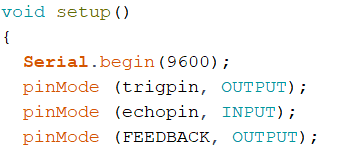
On the start of all Arduino code, there needs to be a “void setup,” which essentially is a command to control what happens upon startup. For the Third Eye, upon setup the trigger pin is set as the “output”, the echo pin is set as the “input,” and the feedback is set as “output” as well.
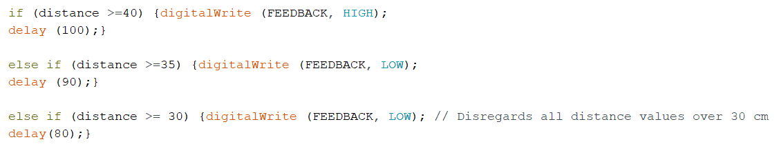
Once the sensor is running, the next set of code is known as “if, else” statements. These lines of code essentially give the Arduino a condition that must be met, and when met will perform a designated task. The else portion of the statement are all other conditional statements; simply, if the original “if” statement is not met then perform the next conditional statement, and if that is not met perform the next one, and so on. For the Third Eye, the “if” statements are conditional upon distance, which takes a variety of ranges in order to vary the delay the pulse of the set feedback. For example, if the distance is greater than 40 cm, turn the feedback completely off; otherwise, if the distance is greater than 35 turn the feedback on and delay by 90 milliseconds; otherwise, if the distance is greater than 30, etc..
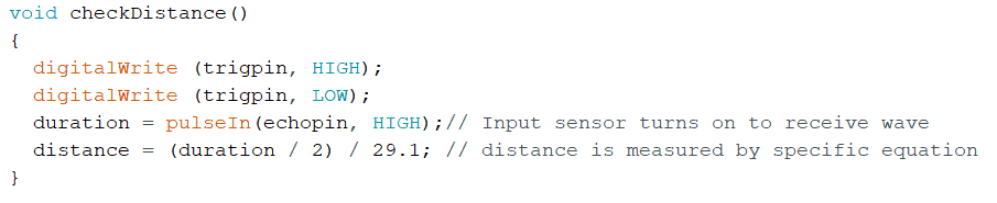
However, the issue was that once the while condition was met, no matter what distance the object from the sensor was, the feedback stayed constant. This was because once in the while function, there was no way out — no way to remind the Arduino that the distance has changed from being under 10 cm. I never included a way to update the value of the distance variable created at the beginning of the code. After doing more research, I found that in Arduino (or any language) you can develop functions which when mentioned can be activated at any time. I then created a “checkDistance” function, which uses the same code within the setup in order to activate the ultrasonic sensor. When this function is placed in the while command, it enables the Arduino the constantly check distance, letting it know that it is no longer within the 0-10 cm range. The Third Eye was now working properly.
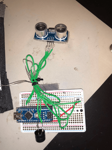
In order to solder together what I had done previously on the breadboard, I simply had to get a perfboard and copy the circuit onto there. Refer to circuit diagram in milestone one. I began by soldering an Arduino IC socket to the perfboard, which is essentially a socket that enables you to place the Arduino on the perfboard without soldering it. After the Arduino was placed, I created the 5v, the D5 pin rails on the perfboard and soldered the ultrasonic sensor to its respective pins. Once the sensor was in I placed the switch on the board and attached the vibrating motor and buzzer. I struggled greatly with the vibrating motor because the positive and negative pins that come out of the motor are extremely weak. After the third time of it breaking, I decided to add hot glue to the connections on the motor in order to increase strength. The soldered perfboard module was now complete.
First Milestone
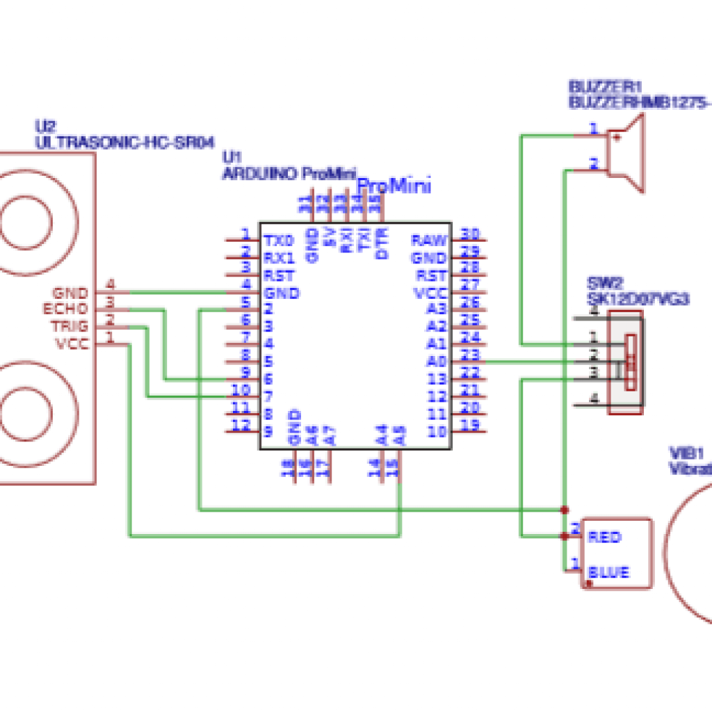
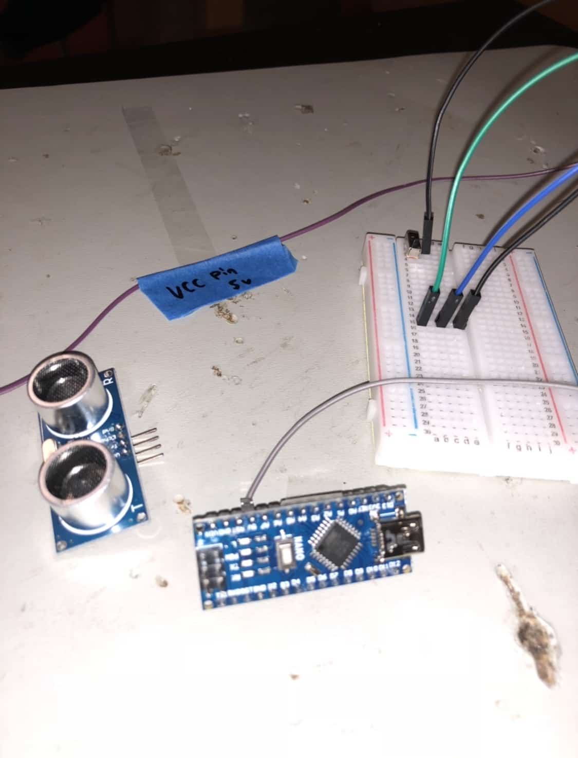
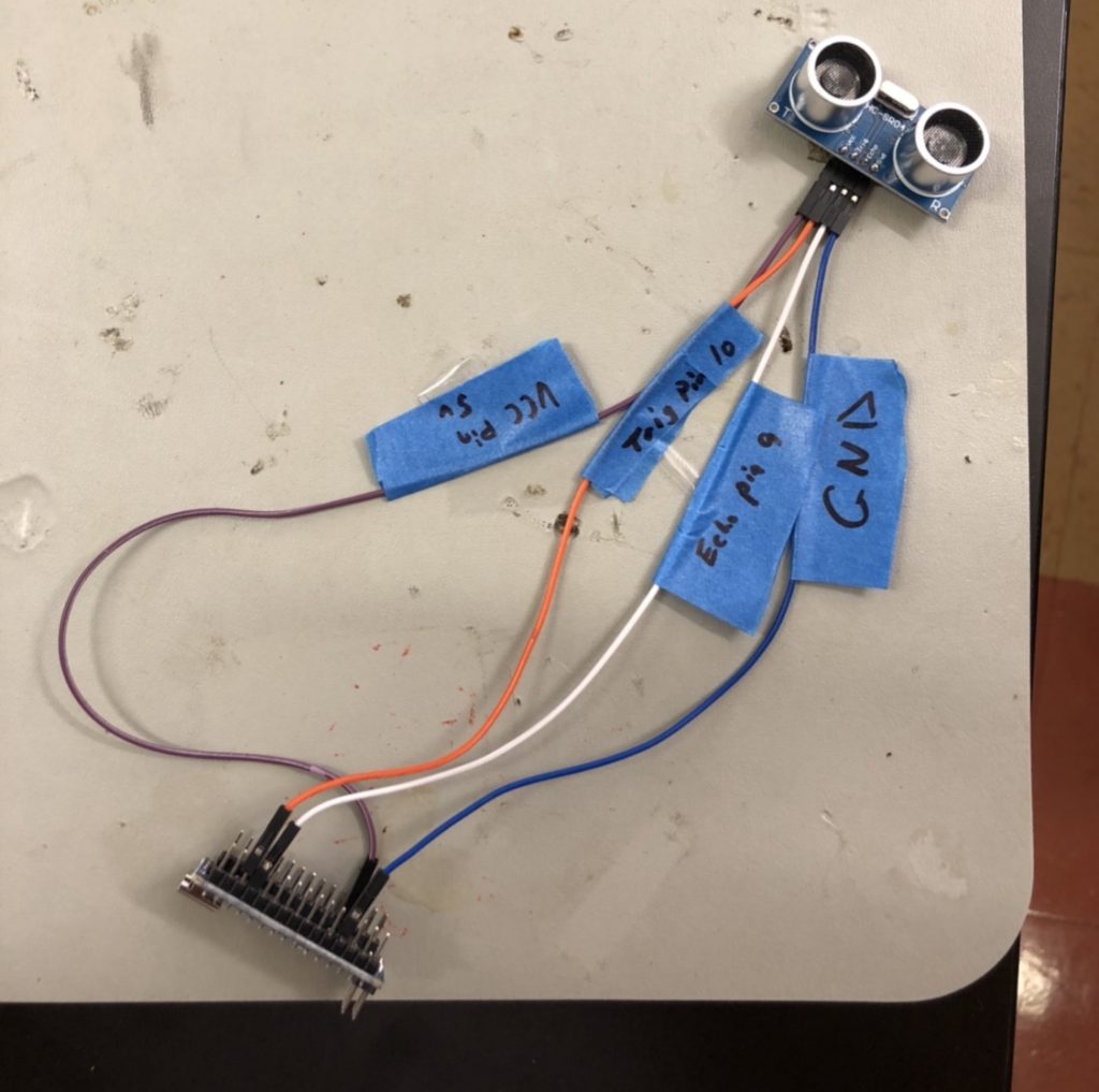
After the schematic came the breadboard. A breadboard is an electrical component that enables you to create a temporary circuit without the need for soldering. I started with the Arduino and the ultrasonic sensor, the two most crucial components of the module. It was my first time working with this ultrasonic sensor as well as Arduino. I found how to connect each respective pin of the ultrasonic sensor to the Arduino: Gnd goes to GND, Echo goes to D9, Trig goes to D10, and Vcc goes to 5v.
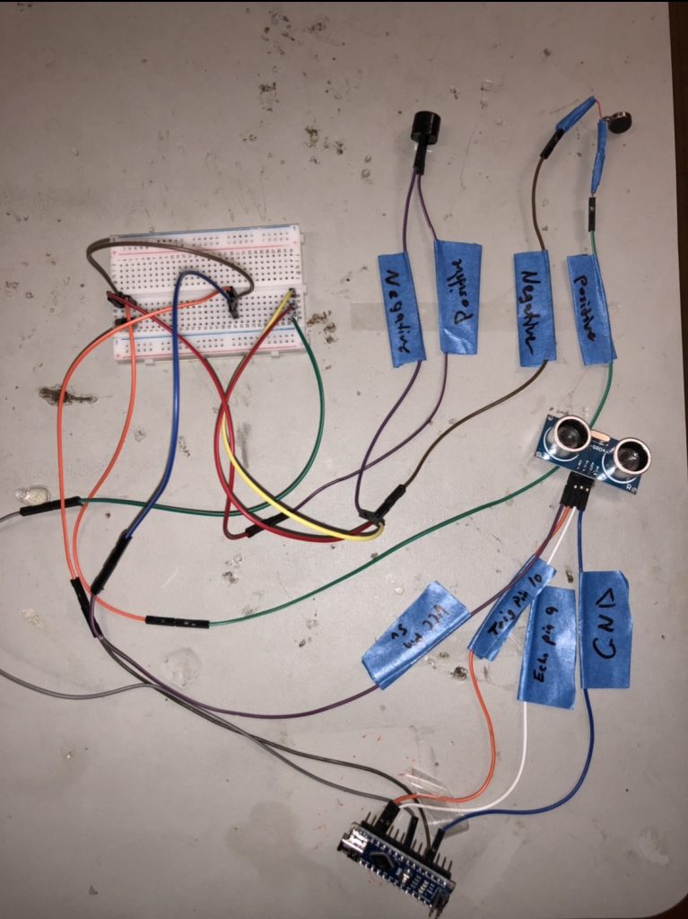
Since more than one component in my design uses the 5v pin, I connected it to its own rail on the breadboard. I added the switch to the breadboard and connected its middle pin, as well as the ultrasonic sensor vcc pin, to the 5v rail.
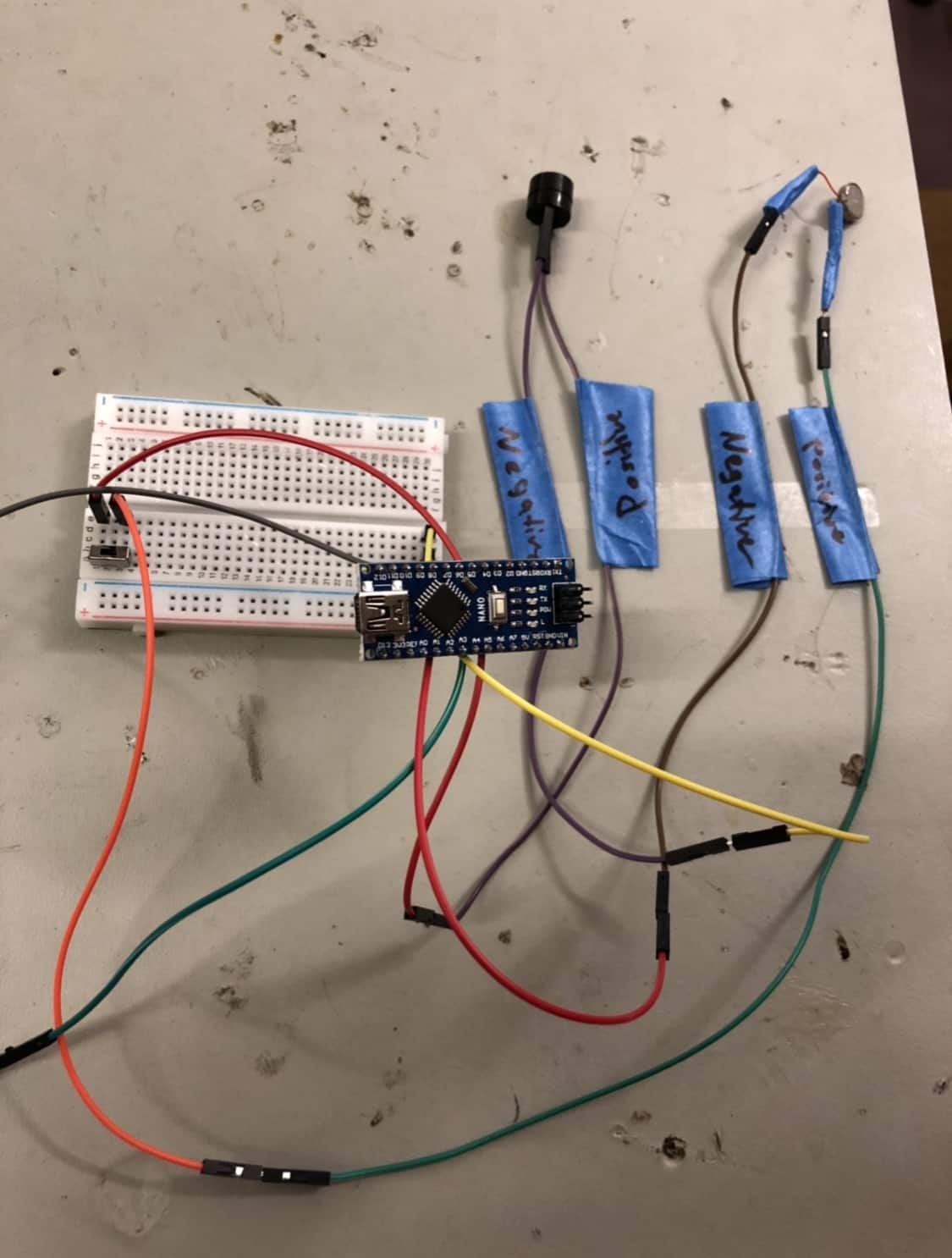
For my main project I am building the Third Eye for the Visually Impaired. It is a replacement to the visual aid currently out there, such as walking sticks or seeing eye dogs. My first milestone is connecting all feedback components to the ultrasonic sensor and arduino. I started designing my main project by developing a digital schematic. Using EasyEDA, a free and easy circuit simulator/designer, I was able to create a digital schematic that accurately represents the physical circuit board of a working module. It was my first time using this website so it did take some time to figure everything out. Nevertheless, after spending the whole day on designing the circuit, I finished with a working schematic.
From then, I added the specific forms of feedback to the breadboard. The positive pin of the buzzer as well as vibrating motor goes to its designated side of the switch ready to receive power. The negative pin on each goes to the D5 pin on the arduino in order to control its form of feedback to respective distances. To achieve this, I connected the D5 pin to its own rail on the breadboard in which the negative pins on both forms of feedback are connected to.
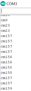
To test that the ultrasonic sensor was working, I researched Arduino code from the developers of the sensor. I used a serial.print command to visually see the distances that the ultrasonic sensor was picking up. To test if the buzzer and vibrating motor were also working, I simply drew power to the arduino and flipped the switch to a respective side and watched as the buzzer beeps or the motor vibrated. All components were working.
https://www.arduino.cc/en/Tutorial/Ping
Tv-B-Gone
The starter project I took part in building was the Tv-B-Gone, designed by adafruit, which is a remote that can turn any TV on or off. The remote uses 2 AA batteries to power a microcontroller which emits over 230 total power codes when button activated, to turn off or on, essentially, any TV within a range of 150 feet. To achieve this task, I used 4 blaster LEDs (light-emitting diodes), specifically IR (infrared) LEDs. Diodes are electrical components that essentially restrict current in one direction. These 940nm wavelength LEDs are commonly used in household remotes. The blue LEDs emit a narrow output (longer range but narrower output) while the white LEDs emit a wide output (shorter range but longer output) This combination of LEDs allow the remote to emit a signal that should hit any TV within the appropriate range. Anyone can use the Tv-B-Gone by a single button press, the only button on the remote.
The button is connected to the microcontroller reset pin, and when pressed resets the microcontroller, emitting all IR codes in its respective library. In order to keep the chip on time when generating its specific waveforms, there is an external 8.0 MHz resonator, in addition to the 8.0 MHz resonator on the chip. A resonator is a device that emits its own electrical signal with a precise frequency, and in this case, keeps the microcontroller stable. This resonator removes the problem of the varying times that take place with battery voltage and temperature. The microcontroller can supply maximum 20 to 40 mA, which is too little for the IR LEDS which have more than 100mA going through them. I used NPN transistors to amplify the power of the microcontroller, as well as turn off currents over 100 mA. This is to prevent damage to the IR LEDs. Furthermore, there are two resistors and capacitors which are used to filter and emit the specific waveforms needed to run the remote appropriately. During the course of this project I learned how to solder components to a circuit board, as well as desolder, for I did make some mistakes during the way. For instance, I soldered the microcontroller before the 8-pin socket, which forced me to desolder and replace the component. However, after all my troubles and accomplishments along the way, I made a working Tv-B-Gone.