RC Tank
My project is the RC Tank, where I use a PS2 controller to move a toy tank that has a projectile launcher. The RC tank also has an ultrasonic sensor to avoid any collision with obstacles.
Engineer
Brian J.
Area of Interest
Computer Science and Computer Engineering.
School
The King’s Academy
Grade
Incoming Senior
Rc tank Demo-night
Second Modification: Projectile Launcher
For my second modification, I made a projectile launcher that uses a DC Motor, to launch the ammo, and screw nuts, which are the ammunition. I attached a wooden block to the shaft, so the wooden block rotates at a high speed like a fan blade. While the block is spinning, screw nuts will fall into the launcher. The rotating block would collide with the screw nuts and the nuts would be forced out of the launcher. To reduce the randomness of the direction the nuts would fly out, I encased the launcher on all sides but the front side. There is also enough space for the wooden block to spin in the encased launcher.
Originally for this modification, I planned on using a small nerf gun. Failing to buy one, or anything similar, I came to the conclusion that it would be much more efficient for me to build it. I started experimenting with wooden boards because I knew it is a good material – thin and sturdy. Because I couldn’t get good idea for my projectile launcher, I started with simply writing down random thoughts that appeared in my head. This was the beginning of prototype one: the spring launcher.
Prototype One: Spring Launcher
This prototype used a pen spring and a wooden block to push ammunition. First, I drew a design on paper where a wooden block, that is attached to a spring, will push the projectile. The mechanism for this launcher is simple; a wooden block that is attached to a spring retracts, then is released to hit/push back a projectile. This is similar to stretching a rubber band, except the spring is inclined to stretch out. I also drew a wooden structure that supports the launch mechanism. The structure has 3 walls and a bottom. There is also a iron rod in the middle of the structure so the spring and block can stay fixed but still retract and stretch. I planned on using a DC motor or a servo motor to retract the spring, however that failed because I lacked the precision and skills to finely cut the small pieces of wood that were necessary. Therefore, I knew prototype one had failed and was not time-efficient to work on it any further.
Prototype Two: Circular Motion into Linear Motion
I still had remaining parts from prototype one and I believed those parts still had their uses, so I wanted to implement them in my second prototype. I started a new design with a DC motor as the foundation of the launcher. Because the motor only produced a circular motion, I needed to come up with an idea to change that circular motion into linear motion. I first thought about gears and how I could use them to shift a wood block or iron rod. I came up with an idea to use multiple wood blocks to transform circular motion into linear motion. I would have a dc motor rotate one block. A second block is attached to the first with an axle. The third is attached to the second, the fourth to the third, and all with axles. The fourth block would restricted by a case, which is from the first prototype to limit the block’s movement (the block slides perfectly within the case). How the blocks work exactly is written/drawn on my design papers.
While I didn’t have any problems making the parts, I faced a problem after assembling them together. The weight of prototype two was too heavy for the DC motor and the tank. The DC motor lacked the strength to rotate a gear and four wooden blocks; the tank’s movement were much slower when the launcher was mounted on the tank. Since the launcher didn’t work and because I believed that speed was important to a RC tank, I decided to discard/disassemble prototype two.
Prototype Three: Simple Rotating Launcher
I came back to my design papers. I realized my thought process may have been too complicated for myself to practice in reality. After placing simplicity as the core of my third prototype, I drew the design for the Simple Rotating Launcher. For easier comprehension, this launcher is much like an electrical fan. After realizing that the DC motor needs gears to rotate heavy objects, I attached only one block to the DC motor. After some experiments, I knew that the a single rotating wooden block could kick the projectiles. To improve the accuracy of the projectiles, I made a support for the motor using remaining parts from prototype one and two. I also enclosed the launcher with cardboard to restrict the randomness of the projectiles’ directions. Prototype three worked and I decided to use it for my launcher. Now I had to make a reloader to prevent the jamming of the launcher.
Reloader
Prototype three by itself worked, but was a manual weapon. To make it more automatic, I decided to make reloader that used a servo. The task of the reloader was simple: to load the launcher with ammo when the ‘shoot’ button on the controller is pressed (I’ve set my PSB_PAD_UP as the shoot button). To accomplish this task the reloader needed two components: an ammo magazine and a mechanism or device that loaded those ammunitions into the launcher. I used screw nuts for ammunition and made a magazine according to the nuts’ sizes. For the mechanism, I used a servo. Initially, I tried to use the servo to push the ammo in the launcher. I changed that thought and used the servo like a gate or door. The magazine would be attached to the launcher on a slant, making the nuts inclined to fall into the launcher. The servo would stop the nuts from falling but would release them when the button is pressed. The making of my reloader turned out to be much easier.


Design Drawings


First Modification: Ultrasonic Sensor
My first modification is the ultrasonic sensor, which allows the RC tank to avoid any obstacles that may obstruct the tank’s path. The ultrasonic sensor is a device that can detect the distance between an object and itself by releasing a sound-wave. The sound-wave that is released bounces back to the sensor after reaching an object; the sensor calculates the distance depending on how long it took the sound-wave to reflect back to the sensor. The tank will use this sensor to detect objects/obstacles that is within 10cm in front of it and when it does, the tank will automatically move backwards until it is at least 10cm away from that object.
Process
I started with testing the ultrasonic sensor on a breadboard. Initially I wasn’t able to comprehend on how the sensor worked or how to use the sensor for my tank. After studying (I searched on Google and on Youtube for help), I began planning on using the sensor as a way for the tank to avoid obstacles. My first step was to momentarily freeze the tank; the tank shouldn’t continue moving when there could be a obstacle obstructing its path. By using an ‘if’ statement inside the control codes, the controller buttons wouldn’t work until the if statement was satisfied. Then I set the ‘if’ statements to rotate both motors in reverse until the sensor detected a distance over 10cm. The code was simpler than I had thought of and managed to finish my first modification.
Final Milestone
Connecting the Remote Controller
The second and final milestone of the project was completing the RC Tank.
From the first milestone, the tank was simply automated and moved specifically according to how it was coded.
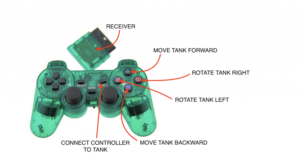
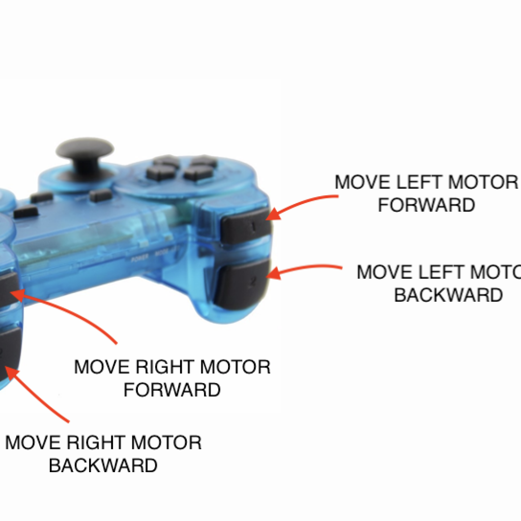
By connecting a PS2 controller to the tank, it became remote controlled; specific buttons on the controller trigger specific movements.
The diagram on the right describes what action the tank will perform based on a button’s input.
How the remote control works for my RC tank can be simplified in three steps. One, the buttons on the controller transmit a signal. Two, those signals are received by the receiver and to the Elegoo. Three, the preprogrammed Elegoo recognizes specific signals and control the motors based on such signals.
Remote Controller Diagram
Process
First, I wired the receiver to the Elegoo (specifics are shown on the right image). The receiver and controller are already preprogrammed so that when powered, they would find each other through signals. The controller requires 2 AAA batteries for power. Then I started to recode the Elegoo. From my previous milestone I had already understood and adjusted myself to the Arduino language. The coding did take time, I didn’t face complications nor bugs. How I coded the Elegoo, to power the motors based on the different inputs provided by the controller, are provided on the right or on the very bottom of this website. With this milestone, I have completed the main project; I plan on starting to work with modifications to add. Currently, I have either a projectile launcher or a sensor in mind as a modification.
First Milestone
Moving The Motors
The first milestone for my main project is simply moving the tank’s motors. The tank’s movement, however, are not remote controlled; the motors move, forwards and backwards, automatically in a loop (continuously forever). When the motors do move, the tank moves along with the motors because the motors are attached to the wheels. What allows the motors to move are the twin-motor gearbox, the Adafruit motor shield (v1.2), the Elegoo Uno R3, and a 6V nickel-metal hydride battery. When the battery powers the motor shield, the preprogrammed Elegoo (the code for the Elegoo is provided on the right) will continuously move the motors forwards and backwards. For my second milestone, I plan on connecting my remote controller, the PS2 controller, to the tank by using the receiver. Since I was able to understand the concept of the motors’ movement while working on my first milestone, I believe that the second milestone will be simple as long as I can connect the controller properly.


Process
I started my main project with the tank chassis. I used the instructions provided on the Bluestamp website and the methods provided with the Tamiya Universal Plate Set. The initial chassis was complete, but lacked the twin-motor gearbox. The gearbox did not arrive as expected and came a few days late. While waiting for the gearbox to arrive, I started to study Arduino code. Arduino was a code language based on C++, which I had no experience using/learning. By the time the gearbox came, I already written a code to move the tank. I assembled the gearbox and then assembled it on the tank chassis. Then I mounted the Adafruit motor shield to the Elegoo Uno, wired the motor shield to the motors in the gearbox, then finally coded the Elegoo. I finished my first milestone and tested the tank. When I connected the battery to the motor shield, the tank moved as coded. This was my first huge step at Bluestamp.
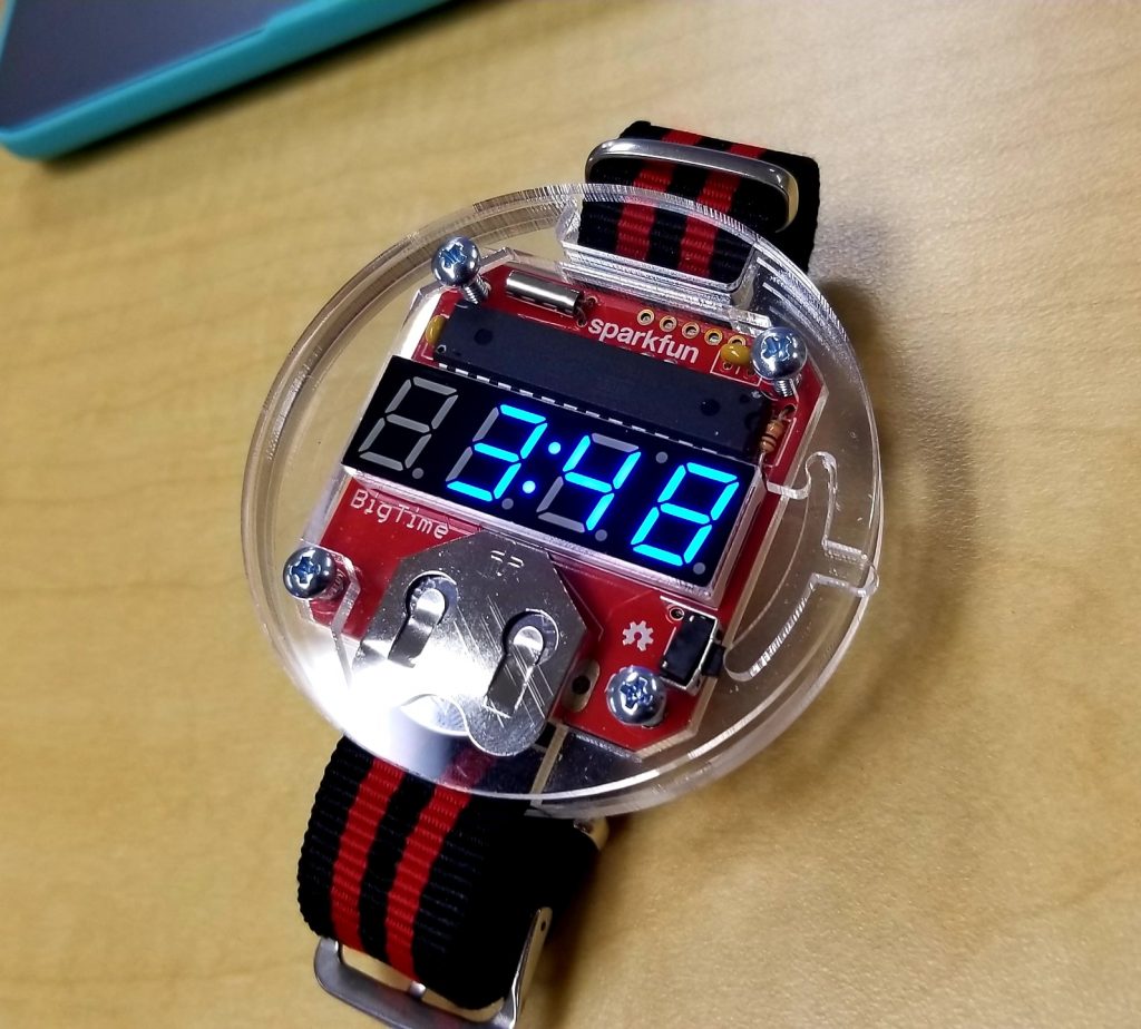
Starter Project: The Big Time Watch
My Starter Project is the Big Time Watch, which is a digital watch that operates on an ATmega328 (a pre-programmed microchip), a 7-segment LED display, a coin cell battery, capacitors, resistors, a 32kHz crystal, and a button. All components of the watch are soldered on to a firmware-based chip; the chip is covered with acrylic covers, which become the watch’s case. The ATmega328 controls the LED display of the watch while the 32kHz crystal manages the timing of the watch. The crystal can release a mechanical resonance by vibrating continuously; the released resonance becomes a electrical signal that has a precise frequency. How fast or slow the watch counts down is dependent on this frequency.Electrical power is provided by the cell battery and the button switches on the LED display (the display turns off after a second button press or after a time of inactivity).
-
Bill of Materials
A List of Materials for RC Robot Tank
-
Build Plan
Step by Step Process of Building the RC Robot Tank
-
Coding the Arduino
Basic Arduino Code for RC Robot Tank (Simply Copy and Paste in Arduino)
-
References
To those who need further instructions/help