3D Printed Prosthetic Hand
This 3D Printed Robotic Hand is controlled using a glove with flex sensors sewn in. There is a wireless connection between the glove and the hand which allows me to control the hand from great distances.
Engineer
Brady M.
Area of Interest
Mechanical Engineering
School
Aliso Niguel High School
Grade
Incoming Senior
Starter Project: Simon Says Game
Overview:
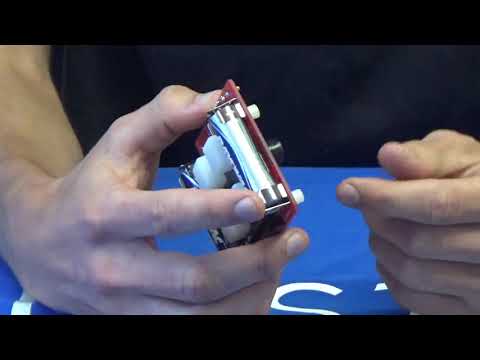
My starter project was to build a Simon Says game. It is a simple memory game where a flashing LEDs indicate an order which the user then has to repeat by pressing the buttons in the same order. How it works is that there is a microcontroller which is basically the brain of the game and converts the inputs (pressing the buttons) to outputs (flashing the LEDs). The ATMega microcontroller, or MCU, is programmed to initially flash the LEDs randomly when turned on until a button is pressed. Once a button is pressed, the MCU interprets this as a cue to start the game, and creates the start of the pattern by flashing one of the LEDs. From then on the user is expected to repeat the pattern being created by the MCU. Every time the user pressed the correct button that follows the pattern created by the MCU, the MCU will then repeat the pattern and add one more random flash of an LED to the pattern. This process will go on infinitely until the user incorrectly repeats the pattern, which the MCU then is programmed to flash lights crazily indicating the failure to repeat the pattern. That is the end of the loop, and it once again flashes lights randomly until the user starts a new game. Finally every part of this project is paired with a corresponding sound. The MCU has the different corresponding sounds programed into it, but the actual sound is controlled by a different switch that turns on and off the buzzer.
Process of Building:
For this project I followed the instructions that came with the kit. The project had three main parts: Assembly, Soldering, and Finishing Touches. First I had to assembly all the different parts into their correct positions, making sure to take in other factors such as polarity. Once everything was placed correctly, I had to solder each part to the circuit board. After correctly soldering the different parts (ATMega microcontroller, buzzer,, 0.1μF capacitor, 10k resistor, LEDs, slide switches, battery clip) I had to finish up the machine by screwing on the translucent buttons over the LEDs to make the buttons light up and each have a corresponding color. Fortunately there were not any big roadblocks that slowed the build process, however I did take time to research and understand the different components of the project. The next step from here is to take what I have learned from this project and apply it to my main project.
First Milestone
Overview:
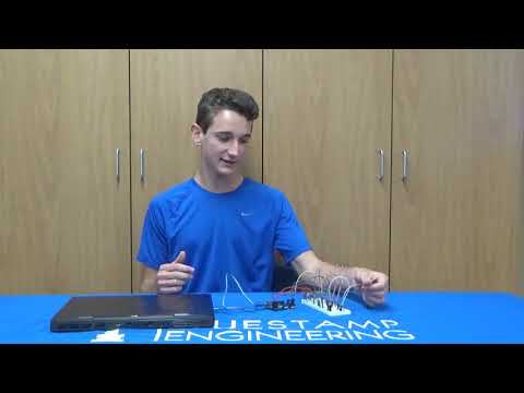
This milestone centered around the flex sensors that will eventually be attached to the glove that is used to control the 3D printed arm. The first part of this milestone was getting the arduino to be able to read a change in the resistance of a flex sensor. I accomplished this by using a voltage divider. Once the arduino was able to determine the resistance in the flex sensor, by knowing the approximate resistance when the flex sensor is unbent, and when it is bent to a 90 degree angle, we were able to determine the approximate degree that the flex sensor is bent at. From there, the next part of this milestone was using these values to accomplish something. For my finished project, it will be turning the servos, but in order to test that I was able to do something with the flex sensors, I first tried it out on LED lights. By coding into the arduino to turn on the LED light if the angle in the flex sensor is greater than 45 degrees, this can be accomplished.
Process of Building:
The first step of building this milestone was learning how a breadboard works. Although I have used breadboards in the past, I gained a much more in depth understanding during the time spent on this milestone. Breadboards are extremely helpful in testing out circuits because instead of soldering connections, the different components can snap into place allowing for the readjustment of parts. This allows us to try all sorts of configurations and fix mistakes easily if mistakes are made. After using an online schematic for a flex sensor in a voltage divider, I rebuilt the circuit on a breadboard. Basically the way a voltage divider works is that it follows the equation Vout = Vin x R2 / (R1+R2). By knowing the voltage going in, the voltage going out, and the resistance of the second resistor (any constant resistor that can be put into the circuit), we can solve the equation for the resistance of flex sensor (R1). So I had to code this equation into the Arduino to read the resistance from the flex sensors. Flex sensors are a unique type of resistor that increases in resistance the more the flex sensor is bent. One side of the sensor is printed with a polymer ink that has conductive particles embedded in it. When the sensor is straight, the particles give the ink a certain resistance. When the sensor is bent away from the ink, the conductive particles move further apart, increasing this resistance. When it returns to flat the resistance returns to original value. After I had the Arduino reading the resistance value and degrees of the flex sensor corresponding to how much it was bent, I wired 4 simple LED circuits to line up with the 4 flex sensors. I then coded into the Arduino a simple if statement that made the lights turn on in each LED if its corresponding flex sensor was bent greater than 45 degrees. The biggest challenge of this milestone was understanding the code, figuring out how to alter the code to my specific setup, learning the syntax of Arduino IDE to implement my own code. Once I got this figured out however, the process sped up significantly. I learned an immense amount through the course of this milestone. Going into this project I didn’t know where to start, knew very little about breadboards, and almost nothing about circuits or Arduinos. After completing this milestone I have now learned how to utilize a breadboard to its full potential, and I am learning so much about Arduinos and circuitry. Although I know I have only scraped the surface and how complex these areas get, I have still learned so much more than I knew before and enough to complete this first milestone.
Second Milestone
Overview:
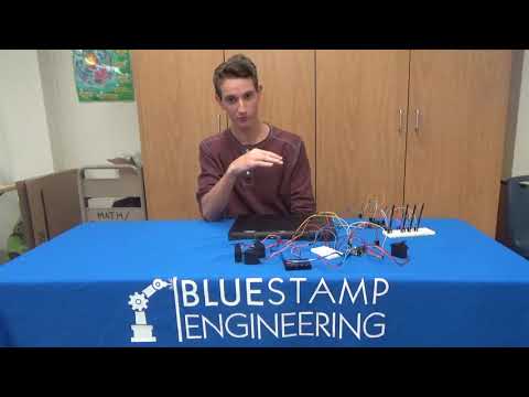
This milestone had two main parts to it. First was the servos and second was the wireless connection using the NRF chips. Basically the goal of this milestone was to get the flex sensors to control the servos wirelessly. What actually happens is that, adding on from the first milestone, one of the arduinos reads converts the resistance from the flex sensors to a degree. It then sends this information to the NRF chip which then transmits it using SPI to the other NRF chip on the other arduino. The second arduino is then coded to interpret these numbers and use them to tell the servos to turn.
Process of Building:
The first major part of this milestone was getting the servos to work. Internally, a servo is mostly just a motor. Incoming pulses tell the motor to turn and the length of a pulse dictates the amount that the servo has turned. There is actually a potentiometer inside the servo that indicates when the position of the servo matches the length of the pulse telling the motor to stop turning. Because of this, it is important to use a pin on the arduino with pulse width modulation or PWM capabilities. These are special digital pins in the arduino which are connected to the oscillating timing crystal, allowing the pin to control the length of the pulses going out, almost mimicking an analog pin. By controlling the length of the pulses going out, it is then possible to control the angle that the servos turn. After wiring a circuit with the servos using the digital PWM pins, I then coded the servos to turn when the angle in the flex sensor is greater than 45 degrees. Eventually the code will allow the servos to turn to specific lengths depending on how much the flex sensor is bent. From here I decided to make the connection between the flex sensors and the servos wireless by using NRF chips. These chips communicate using Serial Peripheral Interface or SPI, which is a synchronous serial communication interface specification used for short-distance communication. Because the flex sensors and the servos had to then be separated, I had to add an addition arduino to run the code for the flex sensors and the servos independently. After rewiring the circuit to include an extra arduino and NRF chips, I finished this milestone by coding the NRF chips to send the data from the flex sensors to the arduino controlling the servos. However, I ran into a problem when sending this information because NRF chips can send over a very limited capacity of information, and the 4 integers corresponding to the 4 flex sensors were too much information to send at one time. To solve this problem, I actually created my own data type known as a struct that allowed me to send the information over. Besides this there were not too many struggles during this milestone besides understanding new code to make the servos and the NRF chips work and a minor short circuit that began frying my breadboard. For my next milestone I hope to calibrate the servos to turn depending on the specific angle of the flex sensor, solder my circuit into a PCB to make it more permanent, and actually construct the 3D printed hand.
Final Milestone
Overview:
This third milestone was basically putting everything together and turning it into what I set out to create. Most of the electronics and code were already in place and instead this part of the project was mainly mechanical. First I had to put the 3D printed parts together and then using fishline, I strung together the fingers with the servos. Then I tackled the challenge of putting all the hardware for the flex sensors on a glove that looked clean and compact while still maintaining the functionality I desired. The last little task of this milestone was calibrating the servos so that they lined up with the correct fingers, bent the 3D fingers when I bent my fingers, and only bent as much as my finger was bending. This was done with little modifications to the code.
Process of Building:
The first part of this milestone, constructing the actual 3D printed hand, proved to be much harder than I anticipated. There is a significant difference between what the design looks like on CAD and what the actual 3D printed product looks like. I had to go to each piece individually and file them down in order to get them to fit and move smoothly. Then tying the fishline turned out to be the most difficult task of all, still providing me with some difficulty after I have already finished the project. In order to get the strings tight enough to pull the fingers through their full range of motion, I had to manipulate the arm into awkward positions. Then when I finally got a string tied tight enough, the crimp would snap because it would be too tight, forcing me to restart the whole process. Through trial and error however I was able to figure it out and get it working successfully. Then putting the flex sensor hardware on the glove surprised me with its difficulty. I tried many different methods such as rubber bands, duct tape, etc. but finally on probably my third attempt, sewing the PCB and arduino onto the glove seemed to be the most effective. I then added a slot for the battery to slide into place and taped the flex sensors themselves onto the fingers of the glove. There is still more that can be done to improve the glove as it is still difficult to put on and some of my sewing has been unraveling as a result of putting the glove on. I hope to find a solution that will allow the glove to be easily put on while not compromising any of the equipment or functionality. From here I hope to continue to improve the durability of the arm and then add on a modification that allows the wrist of the hand to move.