Temp and Humidity Monitor
The Temperature and Humidity Monitor measures the level of heat and moisture. It is created by assembling parts and coding.
Engineer
Billy C
Area of Interest
Computer Engineering
School
Oakland Tech
Grade
Class of 2019- Upcoming Senior
Modifications
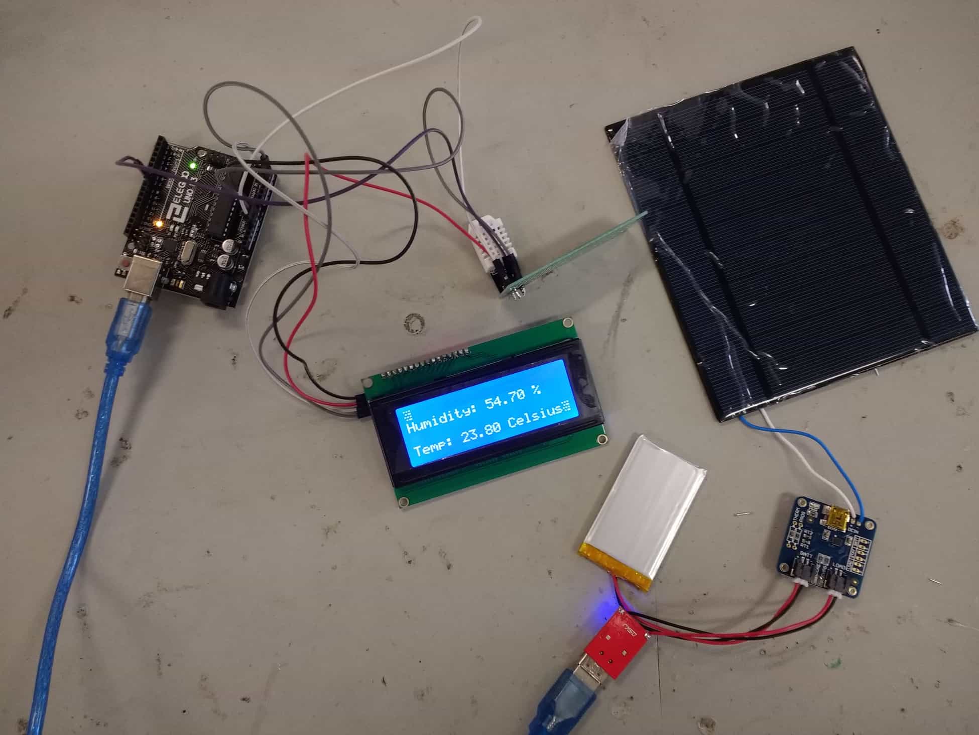
The modifications I applied on my temperature and humidity monitor are adding a solar panel and switching the breadboard with a perforated board. I had to use a power converter from 3 volts to 5 volts and solder it onto another board where the battery and solar panel, which was attached to two wires serving polarized purposes, were connected to. The process works because the solar panel collected a lot of heat and converts it to energy, transferring it into the capacity of the battery. The battery transfers energy through the wires into the adapter, which creates a strong current to power the LCD. I switched the breadboard with a perforated board by removing the jumper wires and soldering them onto the perforated board. Then, I had solder wires to conduct electricity along several lines. After testing both of the modifications, I ended up with a portable and stronger temperature and humidity monitor.
Base Project Milestone
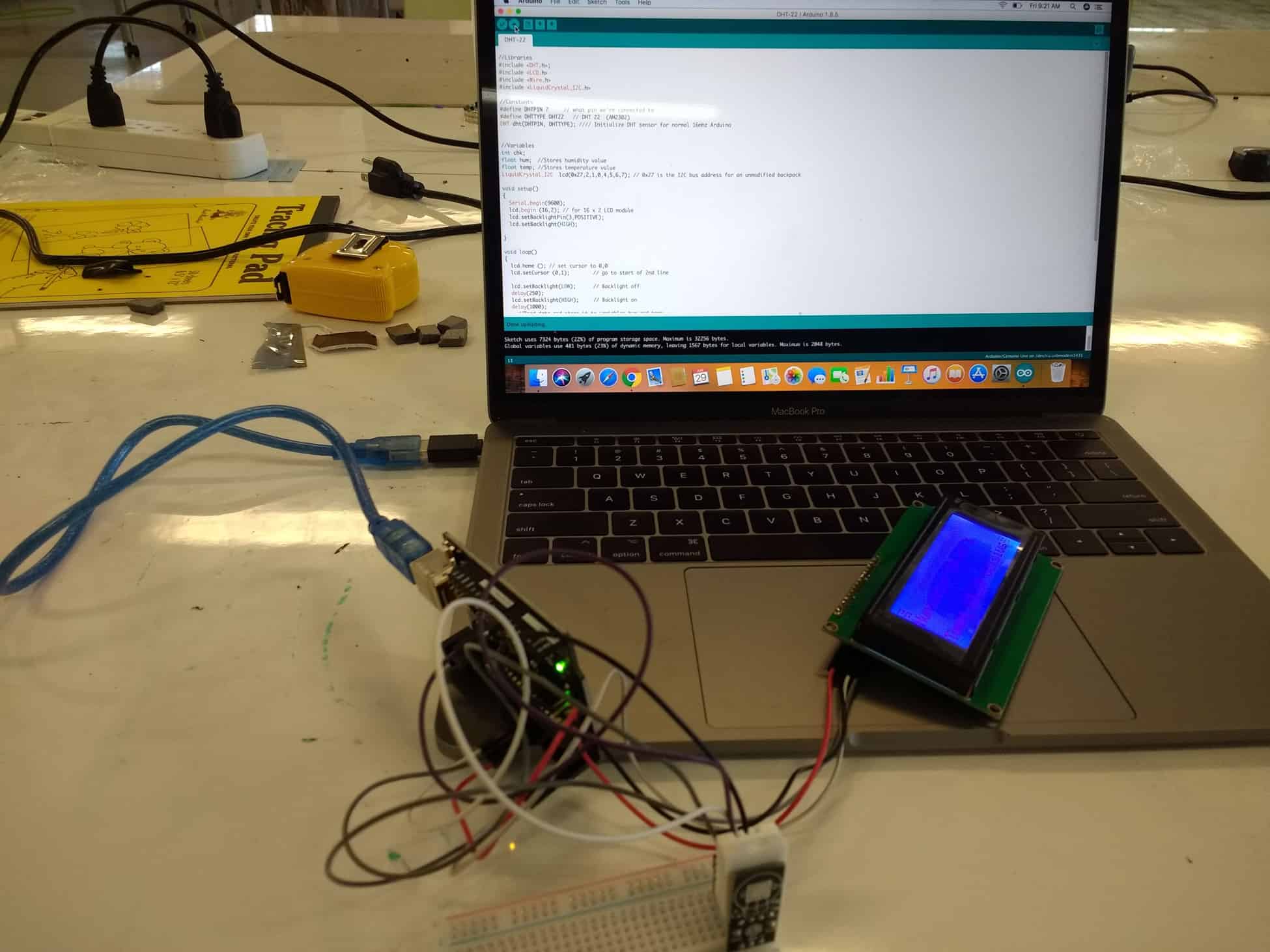
My second milestone was reached through showing temperature and humidity onto my LCD display to the breadboard and Arduino Uno R3 and uploading code onto the Arduino software. I started off from my first milestone by researching ways to apply the data from my serial monitor onto the LCD display. Although the sites only showed generic code, I was able to apply my knowledge of inputting code onto the serial monitor and created a new sketch of code. After connecting the jumper wires onto the backpack module that I soldered into the LCD display, I was able to connect the USB A to B cable into my adapter. The ground wire and VCC to 5v were used for power, the SDA wire was used for data distribution, and the SCL acts as the serial clock Then, I was able to upload the code, successfully completing my project. Some possible modifications for this project are adding time and making the temp and humidity monitor solar powered.
First Milestone
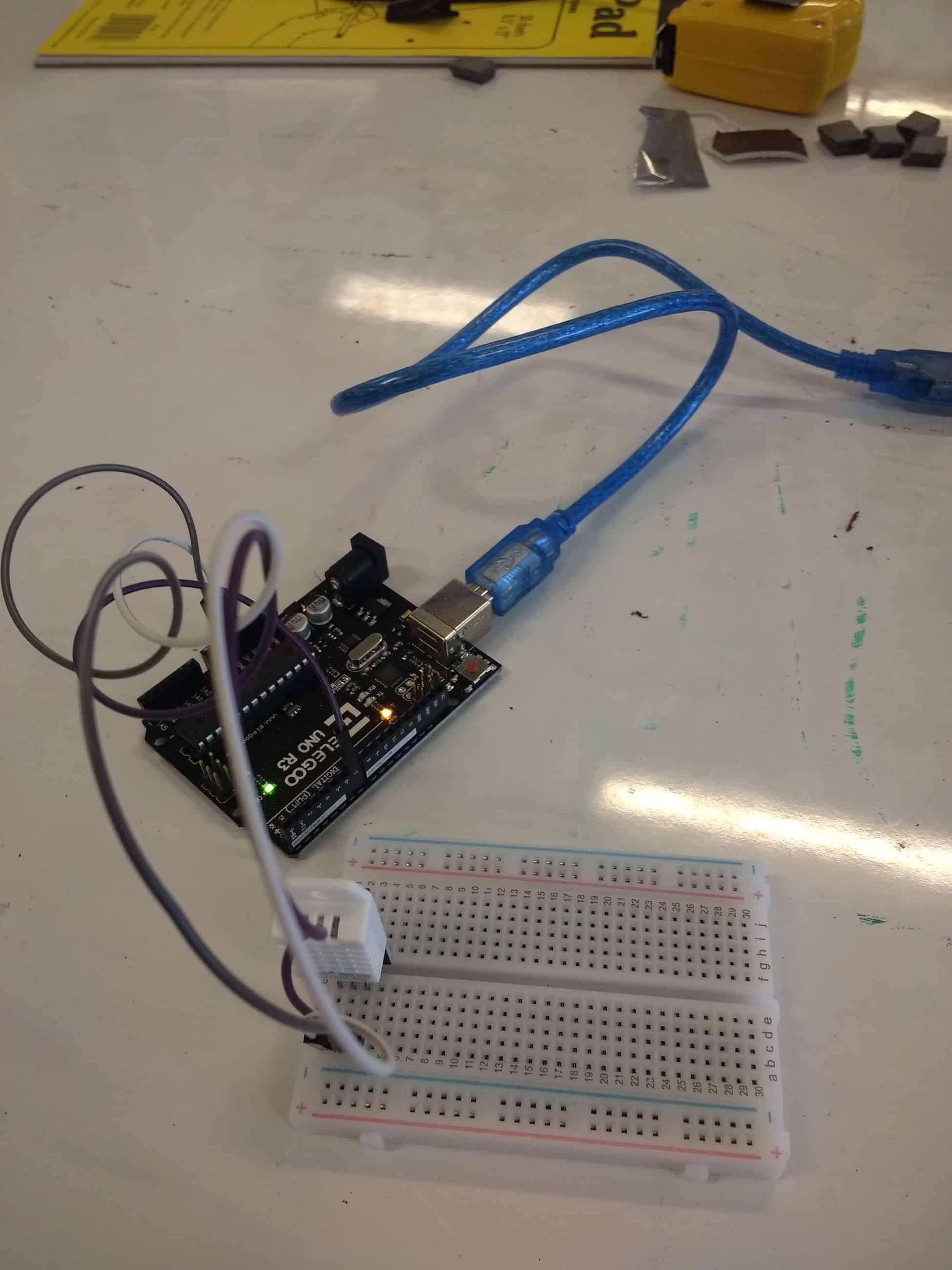
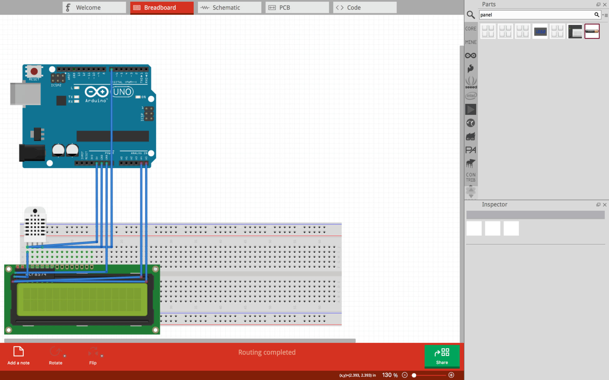
My first milestone is getting the Arduino Uno R3 and DHT22 to transfer the heat and humidity data onto the Serial Monitor. Mainly, I had to connect the middle pin to Digital 7 in order to transfer the data from the DHT22 to the Uno R3. Using other wires to create more connections, I was able to connect all the pieces together and have electricity in needed places when I plugged the USB A to B cable to my computer and the device. Then, I had to use the Arduino software to upload code and libraries on. After correcting the code, I was able to obtain data on the Serial Monitor telling me what the precise amounts were for temperature and humidity.
Starter Project
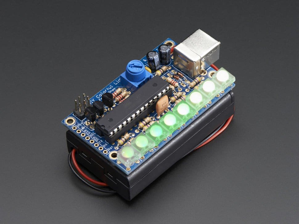
My starter project is the Mini Persistence of Vision 4. The mini POV was created by soldering fourteen resistors, three capacitors, three transistors, one oscillator, a micro-controller, two diodes, and a potentiometer onto a PCB. The resistors play a role in limiting the current flow, the capacitors store energy for consistent electric flow, the transistors act as switches, the oscillator produces an electrical signal, and the micro-controller creates the pattern of the lights. Last, the diodes forces the direction of the currents as semiconductors and the potentiometer is a three terminal resistor that changes the frequency of the waves. When shaking the POV after turning on the switch, colorful waves pop out and twisting the potentiometer changed the rate of flashing. I found this project to be somewhat tedious and stressful because of the mistakes I made including soldering the LEDs in the wrong position where it was very difficult to take them out because of the four terminals. However, the project taught me the importance of each of devices to the process of flashing lights.