The Smart Garden
The Smart Garden is an innovative system which provides optimal conditions for plants, while keeping the involvement for the owner at a minimum. It has sensors that monitor the soil moisture, amount of light the plant receives, and the temperature. When any of these go out of the appropriate range, the system will kick in and either water the plant, give it more light, or notify the owner that it needs a temperature change.
Engineer
Benjamin R
Area of Interest
Bio engineering
School
SAR Highschool
Grade
Incoming sophomore
Reflection
I learned an unbelievable amount on my journey to completing this project. I came in not knowing any of the basic skills involved in engineering. Now, I am better at self-teaching, coding for Arduino, and troubleshooting. The first couple of days working on this project I asked the counselors many questions, but as I progressed, I became more confident and interested in finding problems out on my own. Although I am not sure about my career path, working on this project has taught me that I enjoy engineering. Now, I am confident that I can emerge from BlueStamp and build something on my own.
Bill of Materials – https://docs.google.com/spreadsheets/d/1EmZx3LT0aiGw8ptzUX9DVCaViq-FqpSandQsz4Ali-0/edit#gid=2036955650
Final Milestone
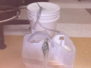
1) For my Final Milestone, I added components that will filter out debris from excess water and recycle it by draining it back into the main water supply.
When I finished my third milestone I thought of how I could improve my project, so I decided to make it more sustainable.
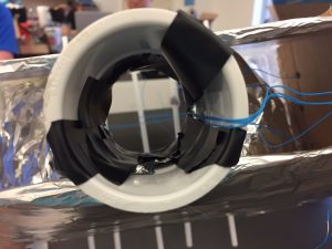
2) If I recycle water the water supply will last much longer without needing to be filled up again by the owner. When the plants get watered, some of the extra water drains through the bottom. I covered the bottom of the plant holders with steel mesh so that only clean water passes through, and the soil stays in.

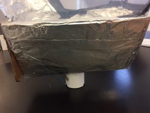
5) I glued the other sides of the cardboard pieces to a small pvc pipe. That covered 2 sides of my funnel.
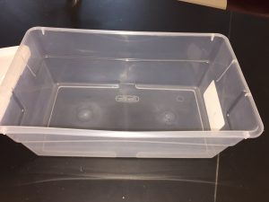
3) Next, I cut off the bottom of my storage container and constructed a funnel to hug the corners of storage container and catch all of the water that drains through the plants.
6) Now the funnel works and the smart garden is complete!
I enjoyed being completely independent in this milestone. I did not follow any directions or even take anyone else’s ideas. This milestone was actually a modification. The modification was all my idea and I liked the idea of improving and making my project better. I think that it is a great way to culminate my days at Bluestamp with something independent. It helped me realize how much I’ve grown in just six weeks!
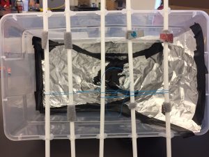
4) In order to create my funnel I measured and cut out four pieces of cardboard. Then I wrapped 2 of them in aluminum foil to make them waterproof. Next, I glued one side of each of the wrapped cardboard pieces to the bottom of the storage container.
7) I cannot believe that I completed my project and I am so happy that it turned out great. I cannot wait to use it and reap my harvest.
Third Milestone
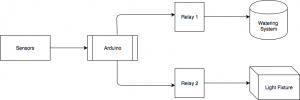
Overview of how the smart garden works
-
Sensors
The sensors receive a current and alter it
-
Arduino
The Arduino receives a current from the sensors. If any of the currents coming from the sensors are too weak, the Arduino sends a current to the relay.
-
Relay
The relay receives the current and turns either the water pump or growth light from off, to on.
-
Water pump + Growth light
Once the water pump and growth light are on, they provide perfect conditions for the plants to flourish. Once the plants have had enough water and sunlight, the pump and light then turn off.
For my third milestone, I completed my base project and have a fully function Smart Garden! I made the code for my LED, water pump, and growth light to turn on and off depending on the values of the sensors.
Below is the code I used to do that. I added very thorough comments to explain every line of code and what its purpose is.
// I included two libraries; both for telling time.
#include <DS3231.h>
#include <Wire.h>
//The temperature sensor is plugged into analog pin 2 on the Arduino, so I started my code off by telling the Arduino what is plugged in where.
int temperatureSensor = A2;
//The LED that reacts according to the temperature sensor is connected to digital pin 2 on the Arduino.
int temperatureLED = 2;
//the moisture sensor is plugged into analog pin 0 and the pump is connected to digital pin 11.
int moistureSensor = A0;
int waterPump = 11;
//Same thing here with the light sensor and growth light.
int lightSensor = A1;
int lightFixture = 8;
// I just declared three variable which I will later assign to the value of the sensors.
int output_value;
int moistureValue;
int lightValue;
//Here I have a couple lines including the bool function which holds true or false values and the byte function which stores an 8-bit assigned number from 0-255.
DS3231 Clock;
bool Century=false;
bool h12;
bool PM;
byte ADay, AHour, AMinute, ASecond, ABits;
bool ADy, A12h, Apm;
//This part of the code is called the setup which only runs once when I initialize the code.
void setup() {
// Start the I2C interface
Wire.begin();
//I’m telling the Arduino to communicate with the computer at 9,600 bits per second.
Serial.begin(9600);
/*In all of these pin mode functions I’m telling the Arduino which pins are outputs and which pins are inputs. The output pins mean that the Arduino is
supossed to send a current out, and the input pins are supposed to recieve currents. For example the water pump is an output because the arduino is suppossed to send
a current out to the water pump. The moisture sensor is an input because the Arduino is recieving a current from the sensor.
*/
pinMode(waterPump, OUTPUT);
pinMode(temperatureLED, OUTPUT);
pinMode(lightFixture, OUTPUT);
pinMode(temperatureSensor, INPUT);
pinMode(moistureSensor, INPUT);
pinMode(lightSensor, INPUT);
}
//This part of the code is called the loop in which the code runs repeatedly.
void loop() {
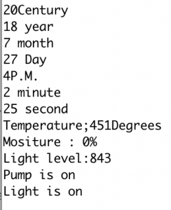
//Next, I use a series of serial.print functions to display certain things on my computer when I open the serial monitor.
/*Since we are currently in the two thousands I told it to display two and for the hundreds digit I told the computer to
display 1 if a century has passed and if not, than to display 0.
*/
Serial.print(“2”);
if (Century) { // Won’t need this for a while.
Serial.print(“1”);
}
else {
Serial.print(“0”);
}
//Then I told the computer to display the word “century” so that I would now what it was displaying.
Serial.println(“Century”);
//Here I tell the computer to display the current year.
Serial.print(Clock.getYear(), DEC);
Serial.print(‘ ‘);
Serial.println(“year”);
// then the month
Serial.print(Clock.getMonth(Century), DEC);
Serial.print(‘ ‘);
Serial.println(“month”);
// then the date
Serial.print(Clock.getDate(), DEC);
Serial.print(‘ ‘);
Serial.println(“Day”);
//I icluded an if statement telling the computer that if the current our is 0, then print a 12 instead.
if (Clock.getHour(h12, PM) == 0)
{
Serial.print(“12”);
}
//Here I used an if else statement. If the hour is less than 12, display A.M.
if (Clock.getHour(h12, PM) < 12)
{
Serial.print(Clock.getHour(h12, PM));
Serial.println(“A.M.”);
}
/*For the else part I told the computer to run the modulo function which gives the remainder.
So I coded for the serial monitor to read the remainder of the current hour divided by twelve.
For example, if it was 15:00, the remainder of 15 divided by twelve is three, so the computer would display 3.
I also told the computer to put P.M. after the hour.
*/
else
{
Serial.print(Clock.getHour(h12, PM) % 12); //Modulo part
Serial.println(“P.M.”);
}
// Next, I made sure that if the hour was 12, the serial monitor would display 12 instead of the remainder of 12 divided by 12 which would be 0.
if (Clock.getHour(h12, PM) == 12)
{
Serial.print(12);
}
//I told the computer to display the minute.
Serial.print(Clock.getMinute(), DEC);
Serial.print(‘ ‘);
Serial.println(“minute”);
//lastly, the second.
Serial.print(Clock.getSecond(), DEC);
Serial.print(‘ ‘);
Serial.println(“second”);
//Now, I tell the Arduino that the variable “output_value” is equal to the value of the temperature sensor.
output_value = analogRead(temperatureSensor);
//Display the word “temperature.”
Serial.print(“Temperature;”);
//Display the output_value which really means the value of the sensor.
Serial.print(output_value);
//Then display “degrees.”
Serial.println(“Degrees”);
// I do a step here similar to the ones I did directly above. I say that the moisture value is equal to the value of the moisture sensor.
moistureValue = analogRead(moistureSensor);
//print the word “moisture”
Serial.print(“Mositure : “);
//”print the moisture value which is really the value of the sensor.
Serial.print(moistureValue);
//Print %
Serial.println(“%”);
// These steps are the same as the ones that are right above, but here they are for the light element of my project.
lightValue = analogRead(lightSensor);
Serial.print(“Light level:”);
Serial.println(lightValue);
/*Next, I did a series of if else statements. The “if” part of this one codes for the LED connected to the
temperature sensor to turn on if the sensor reads below 500)
*/
if (output_value < 500)
{
digitalWrite (temperatureLED, HIGH);
//If the value of the temperature sensor is not below 500 then turn the LED off.
}
else {digitalWrite (temperatureLED, LOW);}
//if the moisture sensor’s value is below 500 then turn the water pump on and display on the serial monitor “Pump is on.”
if (moistureValue < 500)
{
digitalWrite (waterPump, HIGH );
Serial.println(“Pump is on”);
}
//if not, then turn the pump off and display on the serial monitor “Pump is off.”
else
{
digitalWrite (waterPump, LOW);
Serial.println(“Pump is off”);
}
/*if the light sensors are reading below 900 and the current hour is between 5 and 19, then turn the light
fixture on and display on the serial monitor “Light is on.”
*/
if ((lightValue<900) && Clock.getHour(h12, PM)<19 && Clock.getHour(h12, PM) >5)
{
digitalWrite (lightFixture, HIGH);
Serial.println(“Light is on”);
}
//if not, then turn the light fixture off and display on the serial monitor “light is off.”
else
{
digitalWrite (lightFixture, LOW);
Serial.println(“Light is off”);
}
//I put a delay here so that the information on the serial monitor isn’t always changing, instead it displays new information every 8 seconds.
delay(8000);
//Lastly, I told the serial monitor that when it prints new information, to separate it by a line.
Serial.println(“\n”);
}
Problems Encountered
On my way to reaching this milestone, I had even more problems than usual. First, the code for the LED to light up when the temperature goes above a certain level was not working. To identify the problem, I added print statements within my code (it was the same as my test code for my sensors). Then when I click the serial monitor, the print statements cause the computer screen to display the value that the temperature sensor is reading. The value that it was reading was correct so I knew that the problem had to be with my code for the LED. After checking my code I realized that I had the temperature sensor set to the wrong analog pin on the Arduino. Once I fixed it, the LED cooperated according to my code.
Assigning Temperature Sensor and LED to pins on Arduino

Relay ON light
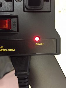
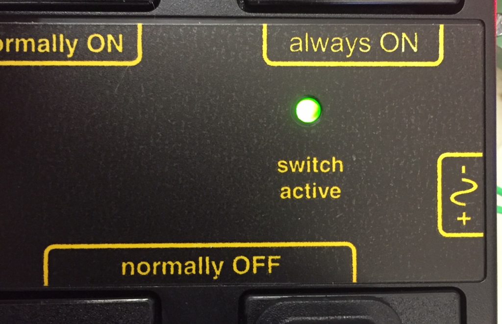
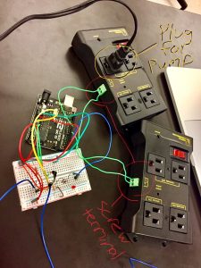
As I continued working on my project, I realized that my relay was not working. There are two lights on the relay: one that lights up when it has power, and one that lights up when the switch turns on. The “power” one was lighting up but the “switch active” one was not .
Switch Active Light
Relay and Screw Terminal
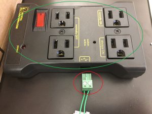
I tested the voltage coming from the wires that were leading to the relay and the right amount of voltage was going there. That told me that the problem had to be after the wires. I was testing different parts of my project, and when I went to take the screw terminal box out of the relay box, the switch light turned on along with the pump. That led me to believe that either the heads of the screws were not sticking out enough or the screw terminal box was not inserted in the right way.
I did both, and then my pump worked, so my problem was solved. Once I moved on from that, I was trying to use DateTime settings on Arduino to tell my growth light to turn on during certain hours. I wanted to use the library DateTime.h but that was not working so I decided to use Time.h instead. When I made the code and ran the serial monitor, it kept track of the time but it did not have the right time. Additionally, every time I disconnect the Arduino from power or run the serial monitor again, the time restarted. I did some research, and figured out that I could add an RTC (Real Time Clock) chip to my system. Since the RTC has a battery, even when I disconnect the arduino from power, it still keeps track of time.
RTC Chip
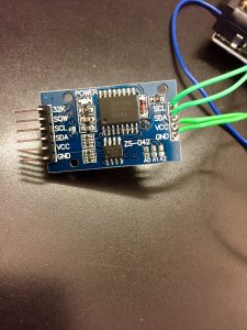
The Time coming From the RTC chip
Once I got the RTC chip, I connected it to the Arduino, but I was getting an inaccurate time and I did not how to change it. I thought that in the library for the RTC there was a place that I could set the time, but I was having trouble opening the library and being able to edit it. Instead I looked up how to do it on Google. I learned that to set the time I had to do it in an example but none of the examples had a place where I could set the time. I added a different RTC library and then I uploaded an example called “set time”. After that, when I ran the code, I was getting the correct time.
When I tested my light code, it worked but since the code contradicted itself (if the light is less than 800 then turn light on, if light is above 800 turn light off) the light kept on going on and off. Once the light turned on, the sensor read above 800 so it turned the light off, and then the light would be below 800 so the light would go on again. At first I fixed it by putting a delay on the function. The light would turn off every 10 minutes, and if it was not getting enough natural light, the light would turn on for another ten minutes. But to be more accurate I decided to angle my light away from the light sensor, so that when the light turned on it would not cause the light sensor’s value to rise.
Reflection
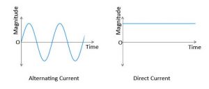
The good part about having so many problems was that I also learned many lessons. I learned a lot more code for Arduino and many new functions. I also learned about AC and DC, alternating current and direct current.
AC V.S. DC
I’ve put a lot of work into this project, and I could not be happier with how it’s turned out so far. I am excited to add modifications where I hope to recycle the excess water that drains through the soil and pump it back to the plants. Additionally, I will add an LED on top of the water bucket that lights up when the water has to be refilled.
Second Milestone
My second milestone was connecting the Arduino to a relay system that will be responsible for turning on the lights and the water pump. Additionally, I connected an LED to the Arduino so that it will light up when the temperature goes above a certain amount. I also set up the lighting system and the watering system. For the watering system, I hot glued a translucent tube to the nozzle of a submersible water pump. Then, I plugged the water pump into my relay. From there, I screwed wires into the screw terminal on the relay and connected the other end of of the wires to digital and ground pins on my Arduino. The code that I will make in milestone 3 will tell the Arduino to send a current to the relay when the sensors go below a certain level. That current will travel through the wires into the relay. The relay acts as a switch. The water pump is plugged into the “normally off” outlet on the relay. When a current is sent from the arduino, it “turns the switch on,” and therefore the pump turns on. To test the relay system I made a code to turn the pump on for five seconds and then off for five seconds.
Watering System
Relay System
Sensors and Arduino Connected to Relay
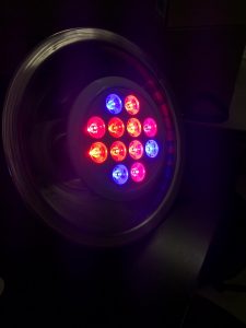
The lighting system is quite similar to the watering one. The grow light is plugged into the normally off outlet on a different relay. That relay is connected to ground and another digital pin on the Arduino. For the lighting system, I used a light fixture that I can clamp onto the ceiling and a grow light with red and blue LEDs. The code that I will make later on will turn the light on when the plant needs it.
Red and Blue LED Growth Light
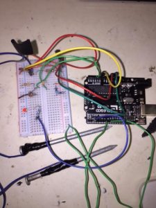
Temperature LED Setup

Setting up the LED was the easiest part of this milestone. I connected the negative end of the LED to ground. I connected the positive end to a resistor which then leads to a digital pin on the Arduino. Just like the lights and the water pump, I will code for the LED to turn on when the temperature goes above a certain level.
On my way to reaching this milestone, I encountered a problem with my sensors again. This time my moisture sensors stopped working. After checking and trying many different things, I found out that there were two issues: 1) there was no connection between the nail and the wire connected to it, 2) there was a mistake in my code. To fix the first issue I had to re-solder the nail and the wire together. The problem with the sensor was that I was reading the value from the temperature sensor instead of the moisture sensor.
On my way to achieving this milestone, I learned numerous lessons and skills. I learned how the longer end of LEDs are the positive end and the shorter end is the positive end. I also expanded my troubleshooting skills. Additionally, I learned how to use a dremel. I used it to cut a hole in the top of the bucket that will contain water. The hole will allow the top to stay on and prevent and water from splashing out, while at the same time allow the tube and plug coming from the water pump, to reach the plants and the relay. Lastly , I developed a newfound sense of independence and perseverance. Progressing through this project made me more confident to tackle problems on my own, without giving up.
This milestone completes the mechanical part of this project, and I’m grateful for this Coding class for kids in New York, and that I made it to this point.
First Milestone
Moisture Sensor
Light Sensor
Circuit Schematic
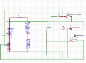
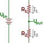
Next was my light sensor. The way it works is similar to how the moisture sensor works. One end is connected to power and the other sends current to the Arduino. I used a voltage divider for it. A voltage divider is a circuit that has two resistors. The voltage between the two resistors is different from the voltage input, and it can be called the voltage output. The equation for figuring out the voltage output is Voutput = (Vinput) R2/R1+R2. The two resistors are the photoresistor and another 10K resistor. The photoresistor can also be called an LDR, light dependent resistor. It is made of a semiconductive material that becomes more conductive in the presence of light. As a result there is less resistance. When more light is shown over the resistor, more of the energy passes through the photoresistor to the Arduino. To get the voltage output, I put a wire in the row that has one end of the photocell and the resistor. I put the other end of the wire in the analog pin 1 on the arduino. To test if the light sensor worked, I used the same test code that I used for the moisture sensor with some slight modifications. After a few tries, the results that came in made sense. I knew it was working because when I shined a flashlight on it, the numbers in the serial monitor went up, and when I covered it, the numbers went down.
Temperature Sensor
Lastly, I made the temperature sensor. It too uses a voltage divider because it has a thermistor and a resistor. Also, the thermistor is made of a semiconductive material. When the temperature increases the resistance decreases and more energy can flow to the arduino.
Problems Encountered
Of course, I ran into some problems on my way to reaching this milestone. The website that I was using for instructions had a link for the test code for the moisture sensors, but the link was no longer available. I created my own code based off of the code from circuits today. When I touched the nails together and ran the code the value should have read somewhere around 985 but it did not. I used a voltage meter and figured out that although I had soldered a wire to the nail, there was no connection between the the two. Then I stripped the wire, and wrapped it tightly around the nail with electric tape. After that, it worked so I was able to move on. When I was finished with the sensors I started my documentation, I tested the sensors one more time, and they were not working anymore. I moved everything to a new breadboard. It still did not work on there so I checked the wires and realized that two wires were in incorrect places. They were in 3.3 volts and 5 volts instead of 5 volts and ground. This made the sensors faulty because they were sending more volts to the arduino then they were supposed to. Since exactly how sensors work is by limiting the voltage, to much voltage made the sensors ineffective. After that issue, everything finally ran smoothly.
Reflection
On my way to reaching this milestone I learned a lot. I learned how sensors work and how they act like resistors. I also worked on my troubleshooting skills. This milestone helped familiarize me with pins on the arduino and their functions, such as the analog pins which can send outputs and receive inputs. Additionally, I learned a little bit about code for arduino. Reaching this point gave me a sense of accomplishment because I had a lot of independence on my journey to it. I worked through the problems and figured them out on my own, and there is nothing more pleasing than seeing what you accomplished.
I’m thankful that I reached this milestone and I’m looking forward to continuing my project at this STEM summer camp for kids.
int sensor_pin = A0;

int output_value ;
void setup() {
Serial.begin(9600);
Serial.println(“Reading From the Sensor …”);
//delay(2000);
}
void loop() {
output_value = analogRead(sensor_pin);
//output_value = map(output_value,0,,100,100);
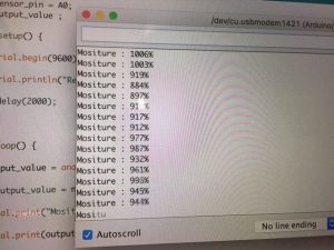
Serial.print(“Mositure : “);
Serial.print(output_value);
Serial.println(“%”);
//delay(1000);
}
int sensor_pin = A1;

int output_value ;
void setup() {
Serial.begin(9600);
Serial.println(“Reading From the Sensor …”);
delay(2000);
}
void loop() {
output_value= analogRead(sensor_pin);
//output_value = map(output_value,0,,100,100);
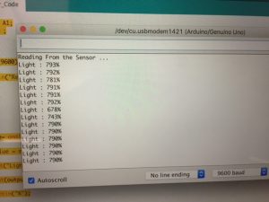
Serial.print(“Light : “);
Serial.print(output_value);
Serial.println(“%”);
delay(1000);
}
int sensor_pin = A2;

int output_value;

void setup() {

// put your setup code here, to run once:

Serial.begin(9600);

pinMode(sensor_pin, INPUT);

Serial.println("Reading From the Sensor ...");

delay(2000);

}
void loop() {
// put your main code here, to run repeatedly:
output_value = analogRead(sensor_pin);
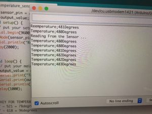
Serial.print(“Temperature;”);
Serial.print(output_value);
Serial.println(“Degrees”);
delay(1000);
}
The Useless Machine
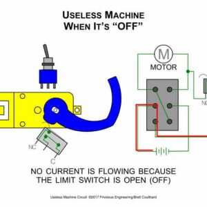
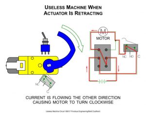
First, the toggle switch is pushed by the user to close the circuit and turn it on. Then, the current travels to the motor and causes the actuator to rotate. Third, a plastic arm connected to the actuator rotates until it peaks out of the door of the box and turns the switch off. Next, the current gets reversed which causes the arm to rotate in the opposite direction. As the arm continues to rotate, it eventually presses down against a lever on the limit switch. Last, when the lever is pressed down, it disconnects the battery from the circuit, and the machine is turned off once again.
The toggle switch is double pole & double throw meaning that it has two different circuits or poles, and each pole can be connected to two different positions. These features enable the motor to spin in two different directions. The limit switch is double pole single throw. Therefore, it controls two different circuits, but there is only one place that the circuit can connect to. When the toggle switch is in its standard position, the motor is not connected to the battery. That causes the circuit to be open, which means that the energy cannot flow to the motor. This happens because the arm of the machine is pushing down on a lever on top of the limit switch. When the lever is being pushed down it causes the circuit to stay open, and the current never reaches the motor. Then, when the toggle switch is flipped, the current is able to connect to the motor. As a result, the arm attached to the motor moves counterclockwise. The arm continues until it hits the toggle switch back into standard position. In standard position, with the limit switch open, the current flows in the opposite direction causing the arm to rotate clockwise. Once the arm rotates further down, it presses down on the lever connected to the limit switch, and once again opens the circuit, causing it to turn off.
Lastly, the LED light functions based on the direction that the motor is rotating. LED stands for light emitting diode. A diode is an electronic component that conducts a current in only one direction. The LED that used had two different diodes. When the motor is spinning counterclockwise, the current passses through a diode that makes the LED emmitt a green light. When the motor rotates clockwise, the current passes through a different diode which produces red light. An LED was perfect to use in this situation because it emits light when an electric current passes through it. Therefore, I placed it in the circuit along with two resistors to limit the amount of current that passes through the LED. The resistors make sure that the correct amount of current passes through the LEDs.
I bumped into numerous problems along the way. My biggest issue was that I couldn’t screw the PCB on top of the motor because there weren’t any holes lined up with the holes in the PCB. I reversed my steps until the part where I put protection pieces on the motor. Then, I carefully followed the instructions until I realized my mistake. I had drilled the protective motor pieces in upside down. After that, my project flowed smoothly until I had to screw the top to the posts. The posts were extremely narrow which made it seem almost impossible to screw the screws in. In the end, all it took was pliers to hold the posts in place and some muscle. In addition to improving my soldering skills, this project helped me develop a better understanding of switches. I learned how the number of poles and throws affects the circuit. I also learned about LEDs and resistors and how to use them.
That’s the rundown of how the useless machine works that I made at a STEM Summer Camp for Kids in New York, and I hope you enjoyed.