
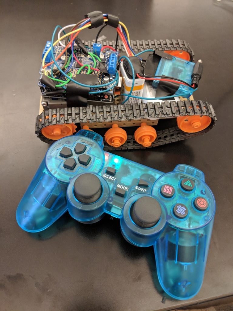
RC Robot Tank
The RC Robot Tank is a project similar to most RC cars with tank treads you can find on the market. The project focuses on power sources like the motor and engines, as well as some programming
Engineer
Benjamin R,
Area of Interest
Mechanical engineering
School
Summit High School
Grade
Incoming freshman
Reflection
When I first applied to Bluestamp Engineering program I felt nervous because I had no prior experience in the field of engineering. Once I arrived at the program, my feelings quickly changed and I began to feel more comfortable. I struggle with problem solving, but the staff were helpful and helped me gain confidence.
When I entered the program the first task I had to complete was learning how to solder. This task helped me gain confidence because I knew I wasn’t the only one without experience in the field. After learning how to solder I felt ready to complete my projects.
My favorite project was my main project, the RC Robot tank. This was my first experience with coding and Arduino. I started the project by assembling the tank. Assembling these parts was difficult, especially the motor. After building the body of the tank I had to connect the PS2 controller to the tank using Arduino. The wiring was complex and I had to stay another week just to find the right code, but these struggles helped me with problem solving and troubleshooting. After completing this challenging project, it was rewarding to know I was able to finish it in the end.
Overall I enjoyed my experience at Bluestamp. I learned many skills like how to effectively troubleshoot and improved my ability to solve problems. The staff were supportive and motivating, and helped me overcome any challenges I faced. I look forward to continuing my education in engineering and attending Bluestamp in the future.
Final Milestone
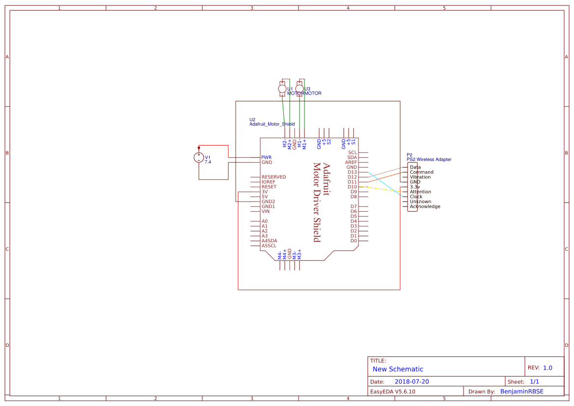
Circuit Diagram
Milestone Video
Stage 1: Arduino & Shield Assembly
After building the base tank it was time for me to move on to the wiring and coding. The first step was assembling the Arduino Uno and the motor shield. using header pins and soldering them onto the motor shield I was able to easily attach and detach the shield from the arduino because the two boards weren’t soldered together directly, which was very convenient for me during the wiring process.
Step 2: Beginning Wiring
Now I just had to complete the wiring. I started by attaching 2 wires to each motor, and connecting them to the motor shield. The motor shield I used required me to connect the wire via screwing it down rather than soldering it to the shield, something I became more and more thankful for as progress continued. After that I connected my power source in the form of a 7.4 volt rechargeable battery pack to the shield and did a quick motor test with an example code from an arduino library I downloaded. This test was a success and from that point all I had to do was get the PS2 controller working with the tank.
Step 3: Connecting the Controller
I knew this would be the most difficult part of the project, and I can’t say I was wrong, but I didn’t expect to be faced with the roadblock that I did. By this point it became clear to me that I had ordered a different motor shield than the one used by the guide I followed, which meant that the code given to me would not be compatible with my motor shield. The way I wired the PS2 to the shield was different from the guide as well. Instead of using header pins, which would have been easier and less messy, I ended up breaking the pins and ended up using wires to make the connection, and soldering the jumper wires to them. Even after checking the wiring and finding a special code for the shield I was using I was still getting no response from the shield. After even more time spent checking the wiring I came to the conclusion that the code was the problem. After many boring hours and many codes tested I finally found one that worked, and I got the controller working. The tutorial I followed to get this to work can be found in the code.
Step 4: Completing the Code, Challenges, and Reflection
As explained before connecting the PS2 controller was an annoying task, but I came across one other big issue, the gearbox. When I started getting the tank to respond to the controller, the motors became a big problem. The gears were moving around inside the gearbox and as a result not making contact with each other, which was necessary for the motor to function. I used spare parts to fill in the gap to stop them from moving around but it seemed that doing this made the other motor stop working efficiently, but this new problem seemed to go away in a few minutes when both motors started working just fine. I’m really happy to say that I finally finished this. I needed a lot of help along the way but I never thought I would be able to get this done in time.
First Milestone
My first milestone for my RC Robot Tank project was the construction of the tank itself. Doing this was quite a challenging task and I had to work hard to build it. I had to do things I had never done before like sawing through the plate to fit the gearbox on. Many of the parts used were small and often fell to the floor while I was working, making assembly take even longer. The hardest part so far was building the gearbox. The parts were small and got lost easily, which was a problem due to the lack of spare parts provided. In the end I’m happy to say I finally was able to overcome such a challenging part of this project.
