Magnetic Levitation

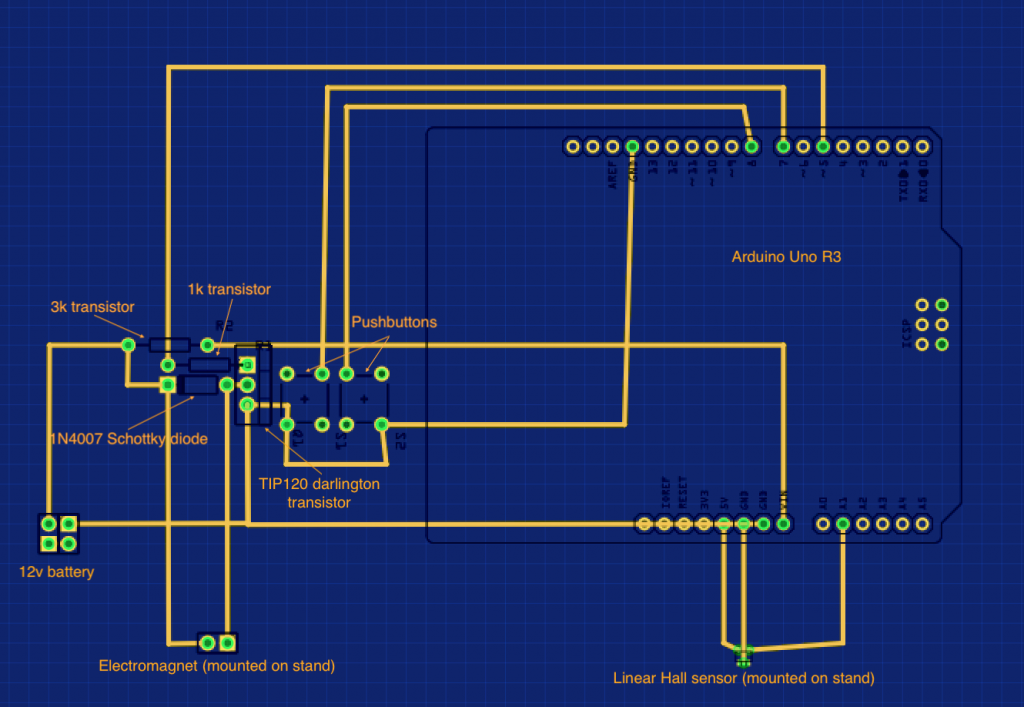
A desk stand that uses an electromagnet and a Linear Hall Sensor to levitate a magnet in place.

Engineer

Benjamin G

Area of Interest

Software Engineering

School

Lynbrook High School

Grade

Rising Sophomore

Final Milestone and Modifications

In my final milestone, I completed numerous minor upgrades to my project. The first of these was to increase the heat dissipation of the electromagnet. After I found out that the major reason the magnet was becoming unstable after a while (~5 min) was because the electromagnet was heating up, decreasing conductivity and making the magnet oscillate. To fix this, I made a modification to the stand itself – I used a dremel to cut slits down the side of the electromagnet holder, which was made of insulating plastic. Secondly, I decided to use a flip switch to turn on and off the entire contraption. I ended up cutting out a section in the corner of the base cover (6 holes total) and gluing a switch there. I had a couple of problems connecting wires to the switch because it repelled solder, So I ended up using solder flux and tape to make the solder stick to the switch. Lastly, I  put in a plug for the battery instead of using jumper wires. Since the plug I decided on was larger than the hole for the power, I widened the hole with the drill and dremel, then filled it with hot glue to hold the plug in place.

Second Milestone

My second milestone is when I mounted the hall sensor and electromagnet on the stand and levitated the magnets for the first time. My first step was to assemble the frame of the magnetic levitation stand using super glue and a file. The stand didn’t fit together well because it was 3d-printed, so I had to file down the insides and edges, then hammer the parts together. After assembling the stand, I positioned the hall sensor and electromagnet on top, and ran the wires down through the column and into the base. With that done, I had to solder the circuit onto a protoboard, then change the levitation height variable in the software. Before moving the circuit from the breadboard to the protoboard, I made a PCB schematic using the Fritzing IDE, then increasing the aesthetics by editing the picture directly. I then followed the schematic and soldered on the individual pieces, which included two pushbutton switches and a high-power darlington transistor. The pushbutton switches were used to allow an extremely small amount of power into two of the pins of the arduino, letting me adjust the levitation values during the testing. Since the transistor had a different resistance (as a semiconductor) depending on how much power I fed it through the arduino, it let me turn off and on the electromagnet using the software and one of the pins on the arduino. I also ended up bridging the gap between parts with short lengths of wire and more solder. After completing the circuit, the magnet wouldn’t levitate because it was shaking too much, so I had to adjust the levitation value manually until I found a value that would levitate the magnet with stability, 409.

First Milestone

My first milestone is when I completed the breadboard circuit using a schematic from the original creator of the project and confirmed that the electromagnet, hall sensor, and Arduino code work as intended. The electromagnet is a tightly wound coil of wire that generates a strong magnetic field by overlaying the magnetic fields that are generated electricity moving through each rotation of the wire, attracting south magnetic poles and metal/repelling north magnetic poles. This is one of the main parts of the circuit, with the rest focused on routing power to the Arduino, which is a development board that holds a microcontroller, and the Hall Effect sensor, the second main part of the project. The Hall Effect sensor, or Hall sensor, detects changes in magnetic field. When a magnetic field is passed close to the Hall sensor, the field exerts force on the electrons and pushes them to the sides. A potential charge difference is built up between the two sides of the semiconductor material, generating a small amount of voltage. The stronger and more polar the magnetic field the Hall sensor is exposed to, the greater voltage it will generate, allowing the Arduino to calculate how close the Hall sensor (positioned 5 mm below the electromagnet) is to the magnet that the electromagnet is levitating.

Starter Project – Mintyboost

My starter project, the Mintyboost, uses standard AA batteries to power a USB slot for a phone charger. In this project, I had to solder multiple parts onto a circuit board, then wire it to an AA battery case.

I started off the project by looking at the labels for the circuit board, then looking at a diagram of the completed product and putting on all of the parts. I decided to solder the smallest parts on first to avoid interference. After soldering the resistors, which were ⅛ W 5% 3.3K, ⅛ W 1% 49.9K, ⅛ W 1% 75K (1/8 W means it can convert electric energy to heat at that rate, or consumes that much, 5% is the amount of resistance the resistor has, and K stands for kilo, and denotes the amount of kilo-ohms of resistance) in order respectively, I put on the ceramic capacitors (Bypass capacitor 0.1uF, or 0.1 micro-Farads, the capacitance of the part) and the schottky diode (1N5818, one amp with a 30 volt rating). After that, I soldered on the larger parts: the power inductor (10uH, indicated amount of inductance) and the two electrolytic (polarized/two way, and one-way) capacitors (220uF/6.3V+, indicated amount of power stored). Lastly, I attached the IC socket (including the chip, LT1302CN8-5, which has a input max of 10V, protecting the chip), the USB type A female jack, and wires to the AA battery holder.

While soldering on the parts, I saw what every part did and how they worked, such as how the resistors allowed a larger current to be passed into the board by using resistive materials to bleed off excess current. I already knew multiple things, such as how capacitors store energy in the short term, or that diodes only allowed current to flow one way, but was didn’t know how other parts worked. For example, I didn’t know how some IC sockets protected their chips in addition to allowing you to plug more in, neither did I know that USB slots had four wires (red for positive, black for ground, white for data input, green for data output). There were other things that surprised me, such as how the power inductor, which stores and converts power to a different voltage, was just a coil of wire.

Overall, this project was fun yet educational, teaching me about all the basic electronic parts and the basics of necessary skills like soldering.

Leave a Comment

Start typing and press Enter to search

Bluestamp Engineering