Omnidirectional Robot
I built an omnidirectional robot that was wirelessly controller by a PS2 controller. The robot is able to move in any direction along the x-axis without turning. While making the it I learned a lot about mechanical and electrical engineering as well as computer science.
Engineer
Ben C
Area of Interest
Engineering
School
Drew
Grade
Incoming Senior
Reflection
Being my first major engineering project, I had loads of fun learning a variety of engineering skills ranging from soldering to coding. It was a nice change of pace needing to find the solution to all my problems on my own. The biggest takeaway I got from BlueStamp wasn’t my robot, but instead the confidence and knowledge I gained. Knowing I can make cool creations like an omnidirectional robot was an amazing revelation. I plan on continuing to create and further exploring the other disciplines of engineering. From BlueStamp I learned that I enjoyed designing and coding. I liked designing because I was able to put my own personal touch on the project to make it truly mine as well as make it look good. When coding, I enjoyed the feeling of creating something from nothing. I also found that I was less fond of electrical engineering. I disliked the tedious checking of wires to make sure they allowed current to flow as well as the lack-luster solder connections I had to constantly replace. However, I can’t wait to start my next project and see where I go from there.
Presentation Night
Final Milestone
#include <PS2X_lib.h>
#include <Servo.h>
Servo motorA;
Servo motorB;
Servo motorC;
PS2X ps2x; // create PS2 Controller Class
int error = 0;
byte type = 0;
byte vibrate = 0;
void setup(){
Serial.begin(57600); //baud rate must be 57600 to communicate w/ reciever
motorA.attach(9);
motorB.attach(8);
motorC.attach(7);
pinMode(9, OUTPUT);
pinMode(8, OUTPUT);
pinMode(7, OUTPUT);
error = ps2x.config_gamepad(13,11,10,12, true, true); //setup pins (in this order) and settings: ps2x.GamePad(clock, command, attention, data, Pressures, Rumble)
if(error == 0){
Serial.println(“Found Controller, configured successful”);
Serial.println(“HOLDING L1 or R1 will print out the ANALOG STICK values.”);
Serial.println(“www.billporter.info for updates and to report bugs.”);
}
else if(error == 1)
Serial.println(“No controller found, check wiring, see readme.txt to enable debug. visit www.billporter.info for troubleshooting tips”);
else if(error == 2)
Serial.println(“Controller found but not accepting commands. see readme.txt to enable debug. Visit www.billporter.info for troubleshooting tips”);
else if(error == 3)
Serial.println(“Controller refusing to enter Pressures mode, may not support it. “);
type = ps2x.readType();
switch(type) {
case 0:
Serial.println(“Unknown Controller type”);
break;
case 1:
Serial.println(“DualShock Controller Found”);
break;
}
}
void loop(){
if(error == 1){ //skip loop if no controller found
return;
} else { //DualShock Controller Found
ps2x.read_gamepad(false, vibrate); //sets vibration motor in PS2 controller to speed based on how hard you press the button
vibrate = ps2x.Analog(PSAB_BLUE);
}
int val=ps2x.Analog(PSS_RX); // reads the value of RX on the the PS2 receiver (value between 0 and 255)
int mapval=map(val,0,255,2000,1000); //reads val, creates a mapval integer between 1000 and 2000 that motor controller reads
int x=ps2x.Analog(PSS_LX); // reads the value of LX on the the PS2 receiver (value between 0 and 255)
int y=ps2x.Analog(PSS_LY); // reads the value of LY on the the PS2 receiver (value between 0 and 255)
if(x==128 && y==127){
motorA.writeMicroseconds(mapval); //stationary rotation
motorB.writeMicroseconds(mapval);
motorC.writeMicroseconds(mapval);
delay(10);
}
int mapx=map(x,0,255,100,-100);
int mapy=map(y,0,255,100,-100); //values from PS2 controller are read from 0-255, read as 100 to -100 value to represent a cartesian plane with a 0 in the center to simplify calculations.
float theta= atan2(mapx,mapy); //
int hyp=sqrt(mapx*mapx+mapy*mapy); //Pythagorean theorem
float cosa=hyp*cos(150*M_PI/180-theta); //
float cosb=hyp*cos(30*M_PI/180-theta); //
float cosc=hyp*cos(270*M_PI/180-theta); //
int Fa=map(cosa,-142,142,1000,2000); //
int Fb=map(cosb,-142,142,1000,2000);
int Fc=map(cosc,-142,142,1000,2000);
if(val==128){ //Fa, Fb, Fc –> rotation
motorA.writeMicroseconds(Fa);
motorB.writeMicroseconds(Fb);
motorC.writeMicroseconds(Fc);
delay(10);
}
delay(50);
}
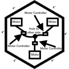
Since I used three motors, I wanted the base of my omnidirectional robot to have sides being multiple of three. Six seemed ideal for me because it was more circular than a triangle and a nonagon wasn’t symmetrical. I cutout the hexagon on MDF using a jigsaw.
Second Milestone
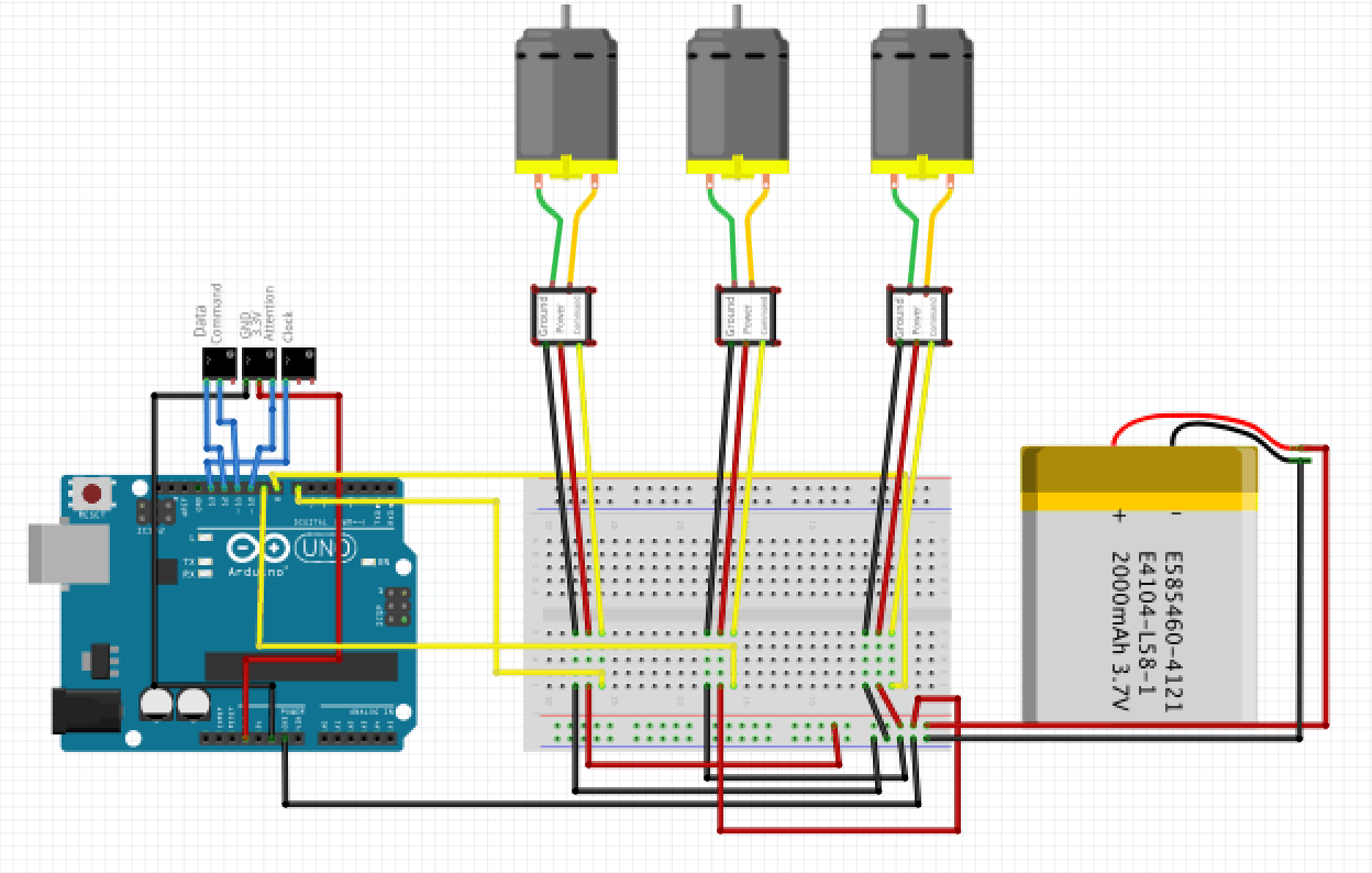
For my second milestone on my omnidirectional robot I connected the PS2 controller to three motors. The first thing I did was connect the wheels to the motors via a drive shaft. Next I connected the Vex motors to the Vex motor controllers. That was straight forward because the motors had pins that would fit perfectly into the motors controller’s ports. After completing my motor setup, I connected them to a breadboard. With the Arduino also connected to the breadboard I lines up the ground power and command cables of the motors to those of the Arduino. This allowed me to write control the motors through the Arduino; which is connected to the PS2 controller. Therefore allowing the motors to be controlled by the PS2 controller. Next I added my battery to the breadboard. This was necessary due to the fact that the motors required more power than the Arduino alone could supply. I got the basic code for the motor control from TechMonkeyBusiness. I changed the code a bit so I could control the motors using both analog sticks.
#include <Servo.h>
#include <PS2X_lib.h>
PS2X ps2x; //create PS2 controller class
Servo ServoN1; //Create servo object representing Servo 1
Servo ServoN2; //Create servo object representing Servo 2
Servo ServoN3; //Create servo object representing Servo 3
int PlyStnRStickUpDn = 0; //Value read off the PS2 Right Stick Up and Down
int PlyStnRStickLtRt = 0; //Value read off the PS2 Right Stick Right and Left
int PlyStnLStickUpDn = 0; //Value read off the PS2 Left Stick Up and Down
int PlyStnLStickLtRt = 0; //Value read off the PS2 Left Stick Right and Left
int ServoN1Setting = 90; //Setting for the Servo 1
int ServoN2Setting = 90; //Setting for the Servo 2
int ServoN3Setting = 90; //Setting for the Servo 3
void setup()
{
ps2x.config_gamepad(13, 11, 10, 12, true, true); //setup pins and settings: GamePad(clock, command, attention, data, Pressures, Rumble)
ServoN1.attach(8); //attatches Servo 1 to pin 8
ServoN2.attach(9); //attatches Servo 2 to pin 9
ServoN3.attach(7); //attatches Servo 3 to pin 7
ServoN1.write(90);
ServoN2.write(90);
ServoN3.write(90);
delay(15);
}
void loop()
{
ps2x.read_gamepad();
PlyStnRStickUpDn = ps2x.Analog(PSS_RY); //right stick up and down
PlyStnRStickLtRt = ps2x.Analog(PSS_RX); //right stick right and left
PlyStnLStickUpDn = ps2x.Analog(PSS_LY); //left stick up and down
PlyStnLStickLtRt = ps2x.Analog(PSS_LX); //left stick right and left
//Readings from PS2 Controller Sticks are from 0 to 255 with the neutral being 128. The zero positions are to the left for X-axis movements and up for Y-axis movements. Variables to carry the settings for the ESCs and Servos The values from the PS2 Sticks are mapped to 45 to 135 degrees
ServoN1Setting = map(PlyStnLStickUpDn, 0, 255, 45, 135);
ServoN2Setting = map(PlyStnLStickLtRt, 0, 255, 45, 135);
ServoN3Setting = map(PlyStnRStickUpDn, 0, 255, 45, 135);
//Write it to the Servos
ServoN1.write(ServoN1Setting);
ServoN2.write(ServoN2Setting);
ServoN3.write(ServoN3Setting);
delay(15);
}
First Milestone
My first milestone for my omnidirectional robot was connecting the PS2 controller to the Arduino via wireless connection. I learned about the different pins in the wireless PS2 receiver. Then I connected each pin the its corresponding port in the Arduino. Data —> 12, command —> 11, ground —> GND, power —> 3.3V, attention —> 10, clock —> 13. After testing to make sure the wires allow electricity to flow I downloaded the base code and PS2 library at The Mind of Bill Porter. The PS2 receiver transmits the signal sent by PS2 controller to the Arduino. With the implementation of the code, Arduino registers each input the user does to the controller then outputs it to the serial monitor.
#include <PS2X_lib.h> //for v1.6
PS2X ps2x; // create PS2 Controller Class
//right now, the library does NOT support hot pluggable controllers, meaning
//you must always either restart your Arduino after you conect the controller,
//or call config_gamepad(pins) again after connecting the controller.
int error = 0;
byte type = 0;
byte vibrate = 0;
void setup(){
Serial.begin(57600);
//CHANGES for v1.6 HERE!!! **************PAY ATTENTION*************
error = ps2x.config_gamepad(13,11,10,12, true, true); //setup pins and settings: GamePad(clock, command, attention, data, Pressures?, Rumble?) check for error
if(error == 0){
Serial.println(“Found Controller, configured successful”);
Serial.println(“Try out all the buttons, X will vibrate the controller, faster as you press harder;”);
Serial.println(“holding L1 or R1 will print out the analog stick values.”);
Serial.println(“Go to www.billporter.info for updates and to report bugs.”);
}
else if(error == 1)
Serial.println(“No controller found, check wiring, see readme.txt to enable debug. visit www.billporter.info for troubleshooting tips”);
else if(error == 2)
Serial.println(“Controller found but not accepting commands. see readme.txt to enable debug. Visit www.billporter.info for troubleshooting tips”);
else if(error == 3)
Serial.println(“Controller refusing to enter Pressures mode, may not support it. “);
//Serial.print(ps2x.Analog(1), HEX);
type = ps2x.readType();
switch(type) {
case 0:
Serial.println(“Unknown Controller type”);
break;
case 1:
Serial.println(“DualShock Controller Found”);
break;
case 2:
Serial.println(“GuitarHero Controller Found”);
break;
}
}
void loop(){
/* You must Read Gamepad to get new values
Read GamePad and set vibration values
ps2x.read_gamepad(small motor on/off, larger motor strenght from 0-255)
if you don’t enable the rumble, use ps2x.read_gamepad(); with no values
you should call this at least once a second
*/
if(error == 1) //skip loop if no controller found
return;
if(type == 2){ //Guitar Hero Controller
ps2x.read_gamepad(); //read controller
if(ps2x.ButtonPressed(GREEN_FRET))
Serial.println(“Green Fret Pressed”);
if(ps2x.ButtonPressed(RED_FRET))
Serial.println(“Red Fret Pressed”);
if(ps2x.ButtonPressed(YELLOW_FRET))
Serial.println(“Yellow Fret Pressed”);
if(ps2x.ButtonPressed(BLUE_FRET))
Serial.println(“Blue Fret Pressed”);
if(ps2x.ButtonPressed(ORANGE_FRET))
Serial.println(“Orange Fret Pressed”);
if(ps2x.ButtonPressed(STAR_POWER))
Serial.println(“Star Power Command”);
if(ps2x.Button(UP_STRUM)) //will be TRUE as long as button is pressed
Serial.println(“Up Strum”);
if(ps2x.Button(DOWN_STRUM))
Serial.println(“DOWN Strum”);
if(ps2x.Button(PSB_START)) //will be TRUE as long as button is pressed
Serial.println(“Start is being held”);
if(ps2x.Button(PSB_SELECT))
Serial.println(“Select is being held”);
if(ps2x.Button(ORANGE_FRET)) // print stick value IF TRUE
{
Serial.print(“Wammy Bar Position:”);
Serial.println(ps2x.Analog(WHAMMY_BAR), DEC);
}
}
else { //DualShock Controller
ps2x.read_gamepad(false, vibrate); //read controller and set large motor to spin at ‘vibrate’ speed
if(ps2x.Button(PSB_START)) //will be TRUE as long as button is pressed
Serial.println(“Start is being held”);
if(ps2x.Button(PSB_SELECT))
Serial.println(“Select is being held”);
if(ps2x.Button(PSB_PAD_UP)) { //will be TRUE as long as button is pressed
Serial.print(“Up held this hard: “);
Serial.println(ps2x.Analog(PSAB_PAD_UP), DEC);
}
if(ps2x.Button(PSB_PAD_RIGHT)){
Serial.print(“Right held this hard: “);
Serial.println(ps2x.Analog(PSAB_PAD_RIGHT), DEC);
}
if(ps2x.Button(PSB_PAD_LEFT)){
Serial.print(“LEFT held this hard: “);
Serial.println(ps2x.Analog(PSAB_PAD_LEFT), DEC);
}
if(ps2x.Button(PSB_PAD_DOWN)){
Serial.print(“DOWN held this hard: “);
Serial.println(ps2x.Analog(PSAB_PAD_DOWN), DEC);
}
vibrate = ps2x.Analog(PSAB_BLUE); //this will set the large motor vibrate speed based on
//how hard you press the blue (X) button
if (ps2x.NewButtonState()) //will be TRUE if any button changes state (on to off, or off to on)
{
if(ps2x.Button(PSB_L3))
Serial.println(“L3 pressed”);
if(ps2x.Button(PSB_R3))
Serial.println(“R3 pressed”);
if(ps2x.Button(PSB_L2))
Serial.println(“L2 pressed”);
if(ps2x.Button(PSB_R2))
Serial.println(“R2 pressed”);
if(ps2x.Button(PSB_GREEN))
Serial.println(“Triangle pressed”);
}
if(ps2x.ButtonPressed(PSB_RED)) //will be TRUE if button was JUST pressed
Serial.println(“Circle just pressed”);
if(ps2x.ButtonReleased(PSB_PINK)) //will be TRUE if button was JUST released
Serial.println(“Square just released”);
if(ps2x.NewButtonState(PSB_BLUE)) //will be TRUE if button was JUST pressed OR released
Serial.println(“X just changed”);
if(ps2x.Button(PSB_L1) || ps2x.Button(PSB_R1)) // print stick values if either is TRUE
{
Serial.print(“Stick Values:”);
Serial.print(ps2x.Analog(PSS_LY), DEC); //Left stick, Y axis. Other options: LX, RY, RX
Serial.print(“,”);
Serial.print(ps2x.Analog(PSS_LX), DEC);
Serial.print(“,”);
Serial.print(ps2x.Analog(PSS_RY), DEC);
Serial.print(“,”);
Serial.println(ps2x.Analog(PSS_RX), DEC);
}
}
delay(50);
}

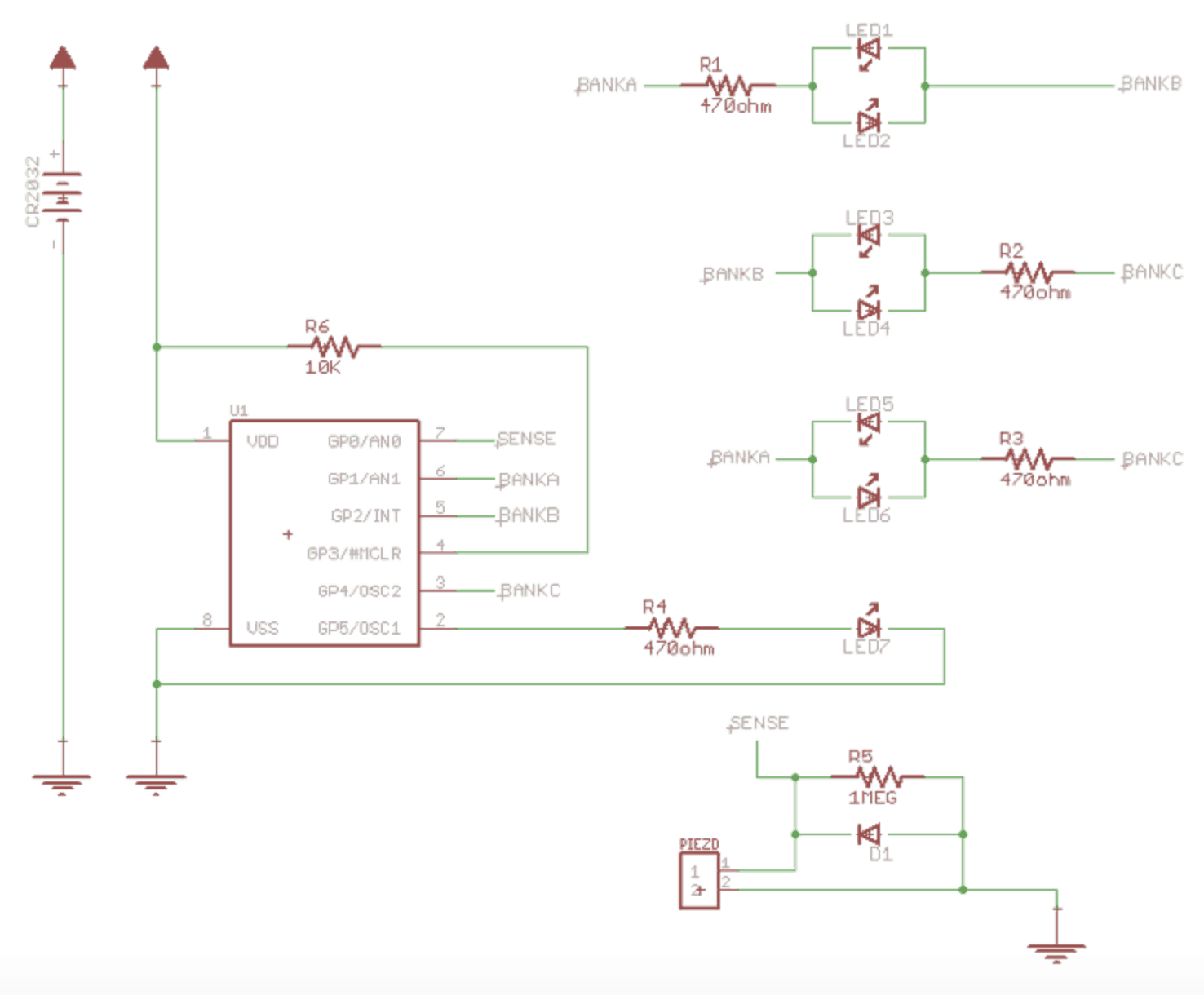
Starter Project
For my starter project I built the Dice Kit from spikenzielabs. When the die is dropped the piezo emits a burst of energy read by the PIC (Peripheral interface Controller). The PIC is programmed to read the least significant variable of the voltage and convert that into a random number between 1-6. The piezo produces electrical volts from pressure or heat. Due to this, each drop produces a new voltage changing the output of the dice. Another key component is the diode. The diode applies low resistance in one direction, extremely high resistance in the other. This allows current to flow in one direction. In order to prevent a short circuit I used one Meg Ohm, one 10k Ohm, and four 470 Ohm resistors.
Schematic and project from spikenzielabs