Mind Controlled Instrument
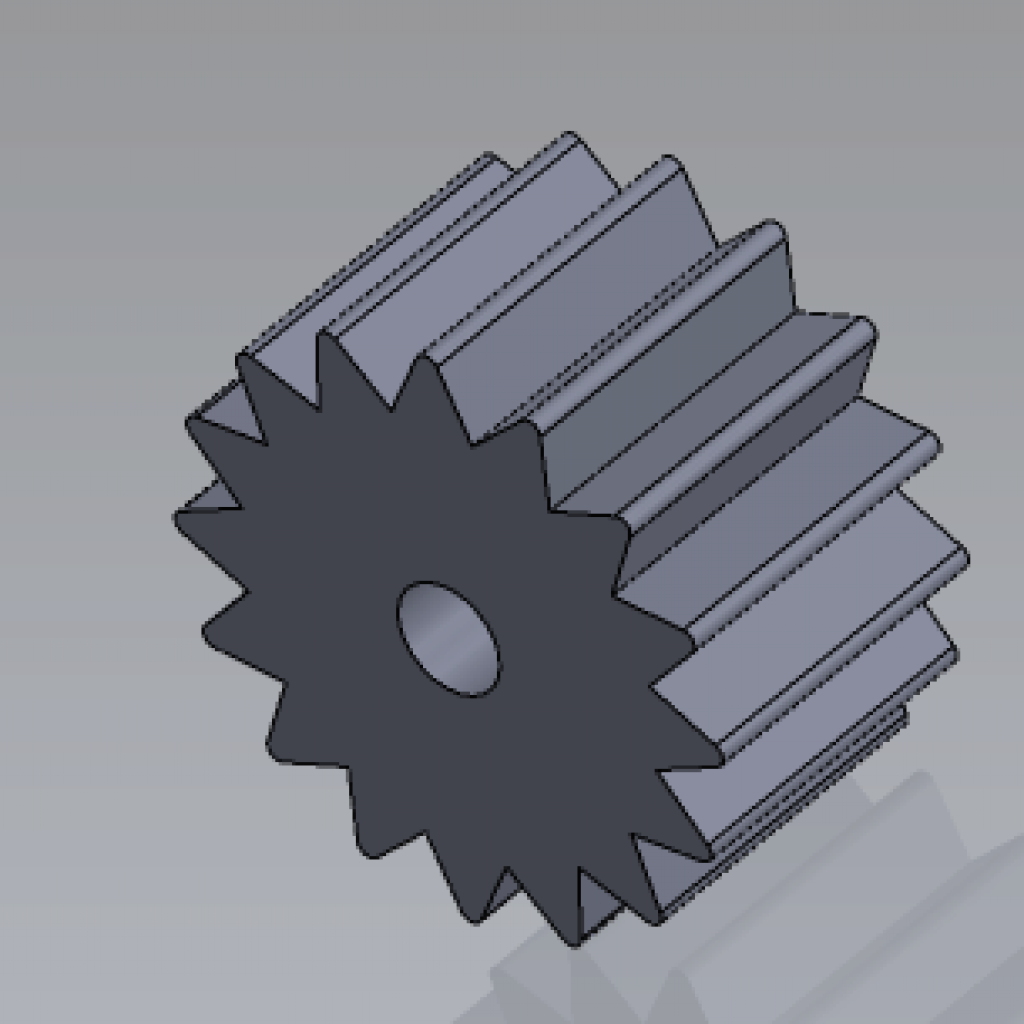
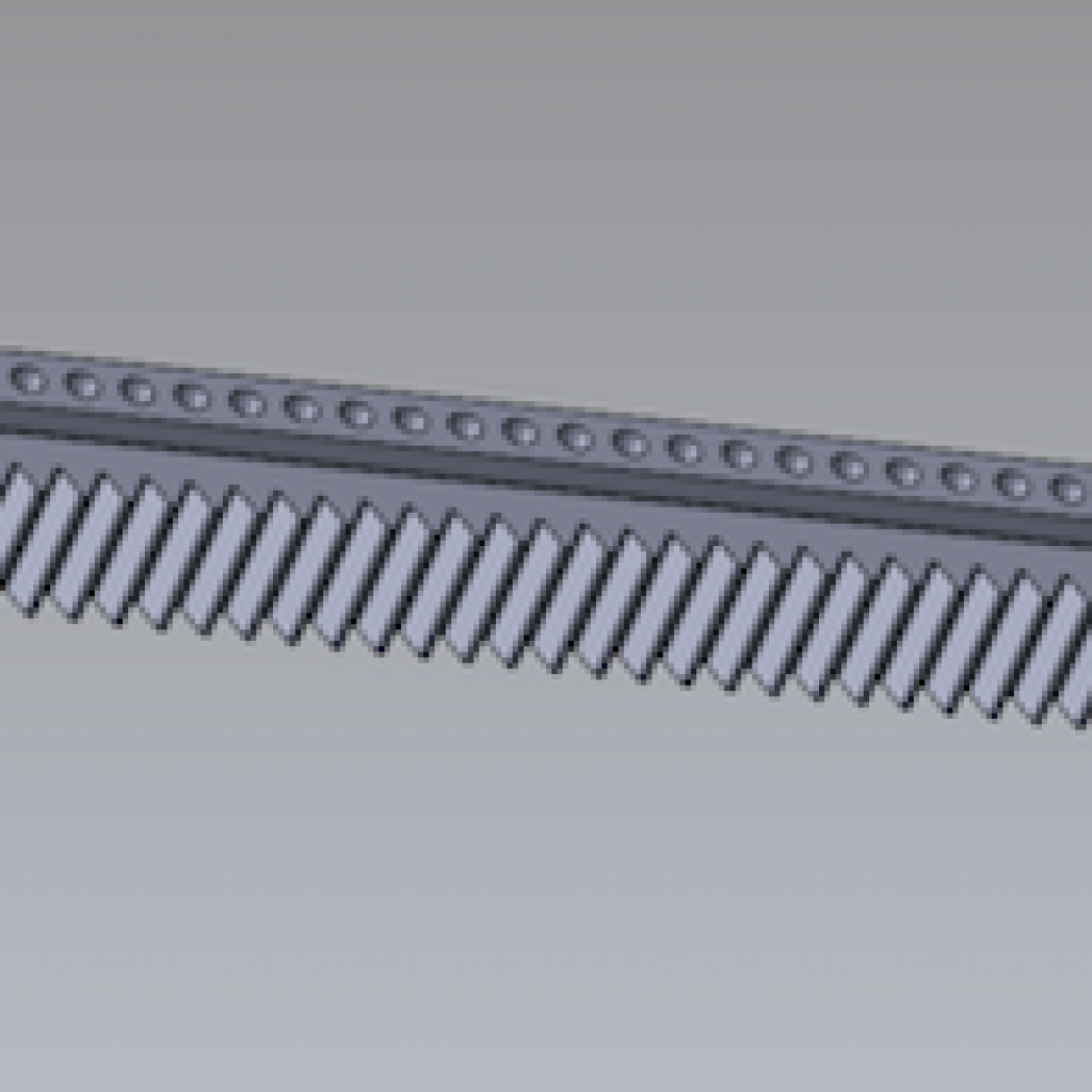
I built an instrument that is played by an EEG headset and a flex sensor glove. The instrument is a harp-like instrument with 8 metal strings attached to a wooden board. On the instrument, there is a 3D printed rack and pinion sliding back and forth depending on what type of brain waves the EEG headset picks up. On the rack, there is a servo that is plucking the strings.
Engineer
Beck S
Area of Interest
Computers
School
Trevor Day School
Grade
Incoming Senior
Final Milestone
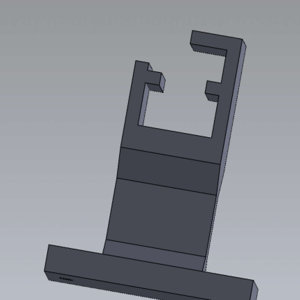
My final milestone has consisted of heavily modifying the whole project. For one, I changed the type of strings on the instrument from nylon to metal. I also added 4 more strings and made a stand for the whole device. The biggest modification I made to the device was the change in my way of playing the instrument. I switched the motors from servos to stepper motors. The stepper motors are bigger and more powerful. I 3D printed a lot of parts to make a linear slide system to play the instrument. I had a rack and pinion and stands to hold up the rack printed.
Reflection:
I struggled a lot with the modifications because many changes required reconstructing the instrument and mechanics. I wanted to use stepper motors instead of servo motors, so I thought at first of using two stepper motors to make a conveyor belt. Realizing that the conveyor belt would not be practical, I had to come up with using a different system. This is where I came up with the linear slide system. I had to get help designing 3D printed parts for my linear slide system. It was difficult to construct parts to fit on my instrument. Another tough part of reconstruction was re stringing the instrument. I tried to make eight nylon strings but they ended up breaking. After the nylon strings failed, I brought in some of my metal guitar strings and used them instead. Luckily, the metal strings worked.
Second Milestone
#include <Stepper.h>
#include <Brain.h>

int val;
int steps = 10;
int dir = 11;
int stepTime = 100;

Brain brain(Serial);
Stepper myStepper(stepTime , 10, 11);

void setup() {
// Start the hardware serial.
Serial.begin(9600);
pinMode(steps, OUTPUT);
pinMode(dir, OUTPUT);
}

void loop() {

// The .readCSV() function returns a string (well, char*) listing the most recent brain data, in the following format:
// "signal strength, attention, meditation, delta, theta, low alpha, high alpha, low beta, high beta, low gamma, high gamma"
if (brain.update()) {
Serial.println(brain.readCSV());

Serial.println(brain.readTheta());
//Serial.println(brain.readSignalQuality());
if (brain.readSignalQuality() <= 80 && brain.readTheta() >= 400000) {
digitalWrite(dir, HIGH);

myStepper.setSpeed(50);

myStepper.step(stepTime / 100);
// digitalWrite(steps, HIGH);
myStepper.step(-200);
delay(stepTime);
digitalWrite(steps, LOW);
delay(stepTime);
myStepper.step(200);
Serial.println("Turn Left----------------------------");
}

}
if (brain.readSignalQuality() <= 80 && brain.readLowBeta() >= 200000 && brain.readTheta() <= 350000) {

Serial.println("Turn Right---------");
myStepper.step(200);
delay(stepTime);
// digitalWrite(steps, LOW);
myStepper.step(-200);
delay(stepTime);
}
}
My second milestone was to make a robotic arm to play the instrument. I did this by putting a servo controlled by the mindflex EEG headset and a servo controlled by the flex sensor glove together with a rod. I then cut out a part out in the instrument board and inserted the mindflex EEG headset – controlled servo into the hole. I then cut out a thin piece of wood to use as a rod. I attached that to the servo and screwed it on. After doing this, I hot glued the other servo controlled by the flex sensor to the other end of the rod. When connecting everything to my computer, the instrument is able to be played. I also drilled the circuit board and arduinos to the instrument to attach everything together. I also worked on my coding so that if delta and theta waves( which are high when one is meditative and relaxed) are high the robotic arm moves to the right and if beta waves( which are high when one is alert and concentrated) are high the arm moves to the left. It is hard to control the arm
#include <Servo.h>

Servo myservo; // create servo object to control a servo

int potpin = A0; // analog pin used to connect the potentiometer
int val; // variable to read the value from the analog pin

void setup() {
myservo.attach(9); // attaches the servo on pin 9 to the servo object
Serial.begin(9600);
}

void loop() {
val = analogRead(potpin);
Serial.println(val);
// reads the value of the potentiometer (value between 0 and 1023)
val = map(val, 0, 25, 0, 180); // scale it to use it with the servo (value between 0 and 180)
myservo.write(val); // sets the servo position according to the scaled value
delay(180); // waits for the servo to get there
}
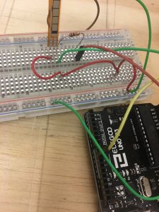
Working on EEG headset control

First Milestone
I built the instrument with a wood board, nylon strings, and screws. I drilled screws into the wood board that act as pegs to attach the nylon strings to. I made it so one can tune the instrument by screwing the screws in and out with a screwdriver.
I modified the headset by opening its circuit board and attaching leads to its transmit pin and a ground( or negative). I drilled a hole through the headset so the wires can go through. I then attached the wires to the Receiving pin and other ground to the Arduino. I had to download a special library in Arduino to control the mindflex eeg headset. I also attached my servo to the Arduino. In the Arduino code, the special brain library allows the brain waves recorded from the headset to be transmitted into data that shows up on the serial monitor. Each brain wave( delta, theta, low alpha, high alpha, low beta, high beta, low gamma, high gamma) and signal strength are shown by numbers and update constantly. The waves fluctuate, so the numbers go up and down. The different waves mean different things, for example, beta waves indicate alertness whereas theta waves represent relaxation. I made it so that when the data numbers from the beta waves are high, the servo will move.
I also made a flex sensor glove that will control the sweeping motion of the robotic arm. I had to make a circuit that had the flex sensor control the servo with an Arduino. I soldered this circuit onto a permanent breadboard. I then took a glove and sewed the flex sensor it.
Starter Project- Minty Boost Phone Charger
My Starter Project is the Minty Boost Portable Charger. It allows one to charge phones and gadgets with USB port charging. In order for the charger to work, it requires two 1.5 voltage batteries which is then converted to 5 volts from a boost converter circuit. This circuit consists of the following parts: an LT1302 chip, 2 power supply capacitors, 2 bypass capacitors, 2 15K 1/4W 5% resistors, a 100K 1/4W 5% resistor, a power inductor, and a Schottky Diode. The voltage is converted from 3 volts to 5 volts using a boost converter inductor and a constant flow of current, but then, when a usb is plugged into the machine, a switch is then turned on, forcing the current to go to the diode. The current will build up in the chip, storing 5 volts of power.