3D Printed Robotic Hand
I am building a robotic hand, which mimics the movements of my own hand using sensors attached to a glove. Much of the materials will be 3D printed, while the remaining parts were bought from various locations on the internet. This build was inspired by a student who posted his creation on Instructables. I used many of his schematics and modified some of his code while creating my own project.
Engineer
Bates B.
Area of Interest
Computer Science and Robotics
School
Los Gatos High School
Grade
Incoming Senior
Reflection
I took my opportunity at Bluestamp to not only learn how to use tools like the soldering iron and dremel, but I also expanded my ability to self teach myself. I came into Bluestamp with very little knowledge of mechanical and electrical engineering, but I almost immediately started learning through hands on experience. The very first thing we learned was how to use a solder iron to keep wire connections on circuit boards secure. We did not learn through a lecture or video. Instead, we were given the soldering irons to figure out the best ways to use them. This type of hands on experience continued throughout the program, where we would learn through doing. In the cases when we absolutely needed to figure out information or strategies, we were encouraged to use the internet to look it up ourselves without the instructors simply telling us the answer. I can say with confidence that this has made me more self reliant and knowledgeable about the topics than if I were spoon fed the answers. I came out of Bluestamp with many skills that I lacked coming in, and I loved the opportunity to obtain hands on skills with engineering.
Final Milestone
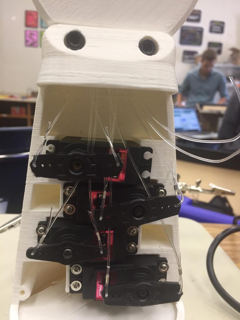
Arm Internals
Robotic Hand
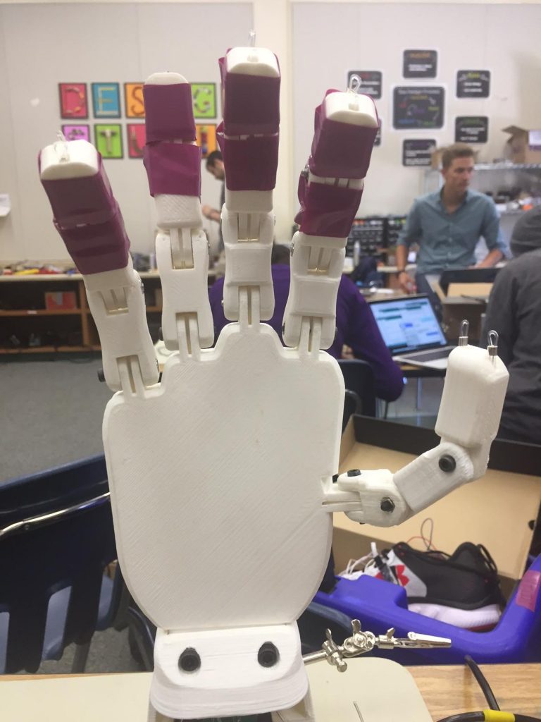
For my third milestone, the final milestone of the intensive project, I assembled my hand and connected it to my circuitry that I have already made.
I started off with the 3D printed pieces, divided up into the hand, finger pieces, arm base, and arm cover. The first step I took was screwing the pieces of the fingers together. After I attached them together, I started attaching the fingers onto the hand. However, that is when I ran into my first problem. Two of the parts that I received were the wrong pieces, and they did not fit into the hand as they should. Luckily, I was able to invert the positioning of the part and it still worked as it should have, although the aesthetic of the hand suffered as the pieces were not symmetrical.
After I finished attaching the fingers, I began to run fishing line through the holes in them. This fishing line, when pulled, flexes the fingers in one direction or the other. Unfortunately, errors in the 3D printing resulted in blocked holes in some areas, but I opened them up by inserting crimp tubes, strong thin metal pieces, first, then threading fishing line after.
However, I quickly found a problem with the joints of the thumb. Suffice to say, it did not flex like a real thumb would. When a real thumb would curl into the palm of one’s hand, the robotic one would remain straight while it turned slightly into the palm. When flexing the other way, it would curl into the side of the hand instead of being straight. I tried many ways to fix this, such as inverting pieces of the thumb, but it didn’t work. I eventually discovered that the first piece of the thumb switched the sides of the thumb that the wires ran, producing the odd flexing motion, so I tried to re-switch them. Unfortunately, there wasn’t enough room for the line to alternate, so that idea did not work either. Regrettably, I was not able to find a solution for the problem. It was produced by a design flaw in the part that I was not able to fix. If I were the designer of the 3D printed pieces I would have made it differently, but as I am using someone else’s parts I just have to accept the flaws inherent in it.
Moving on, I attached the hand to the arm piece, and attached the servo motors, motors that turn to a specific given angle, to the arm as well. Here I encountered another problem with the design. For some reason, there is only enough room for four servo motors. Each servo is attached to a finger, so having only four servos means that only four fingers can be controlled. I have no idea why the designer of the parts made this decision, but it is definitely something I will fix in the future of my design of this project. Then, I crimped the fishing line to the servo motor horns, pieces that attach to the servo to allow the line to attach to it. I attached to the servos, allowing the servos to flex the fingers that they were attached to. The provided servo horns did not fit within the arm, so I used a dremel to reduce their diameter to a workable size.
After testing the servos and how they flex the fingers, I encountered yet another problem. The servos pull the fingers by spinning a horn with the string that connects to the finger attached. The problem is that they do not pull the string far enough. This results in incomplete movement of the fingers. For example, instead of making a fist, the hand makes a claw. There was not enough room in the design to increase the width of the servo horns, meaning that I am unable to increase how much the finger is pulled. This is yet another flaw in the design of the 3D printed parts that I have to work with. Since I am unable to make the string be pulled further, I figured out that I could decide which joint of the hand I wanted to rotate most. I’d prefer to have an almost-fist rather than a claw at most, so I taped on screws to the top two joints to remove their degree of freedom. As the top two joints could no longer rotate, the bottom joints rotated instead, using the force of the strings. Even if it is not a perfect solution, it is much better than the original way it worked.
Finally, I tried to attach the cover for the arm that hides the servos and strings. However, it does not fit onto the arm. Even if it did fit onto the arm, the servo horns would be in the way. Basically, it is another design flaw of the designer of the arm that I have to work around. In the end, I decided to just not include the cover, as it serves no function other than aesthetic, and I enjoy the look of an uncovered arm piece anyways.
Throughout the assembly of my hand, I have discovered many problems inherent in the design of the parts. From the thumbs weird way it flexes to there not being enough room to have a fifth servo (for the thumb), the hand is unable to function effectively. If I were the one who designed the pieces, I would have many changes that I would make. First off, I would not invert the wires within the thumb, allowing it to flex in a manner that is more close to how an actual thumb works. I would also allow more room in the arm piece, both to allow servos to actually pull the fingers all the way, and to allow room for the fifth servo motor. Finally, I would make the arm covering actually fit onto the arm.
Second Milestone
Circuitry
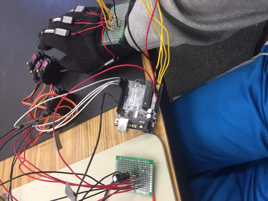
For my second milestone, I have finished sewing the required circuitry onto my glove. In order to do this, however, I needed to finalize my circuitry in the first place.
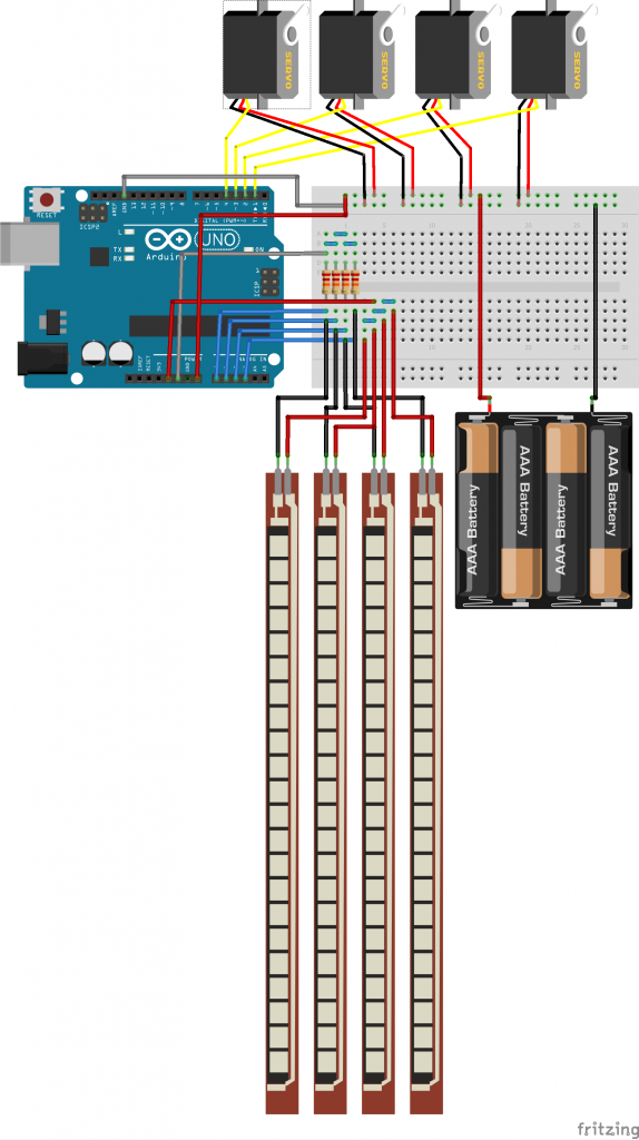
I started off with removing all of my wires from my breadboards, parts that are used to hold wires together, and de-soldering my parts from the wires they were temporarily connected to. Then, I used Fritzing, an application dedicated to designing circuitry, to plan what my new circuits would look like. I decided to have two different circuit boards, one for handling the flex sensors, one for handling the servos.
After I was done planning, I put my designs to the test. Using solid core wires, filled with a single piece of metal, I connected my circuit to the various parts of my project. In addition, with my new design the Arduino, a micro controller, takes power from the battery, meaning that I don’t need to connect my computer when it needs power.
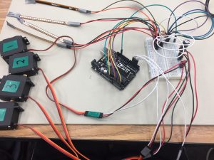
After I finished making my circuit, I required pieces onto my glove. Each flex sensor, a long strip that outputs how far it is flexed, was connected to it’s corresponding finger, and I sewed the circuit board onto the wrist of the glove. Now, when I flex one of my fingers the flex sensors are flexed, and the servo motors respond accordingly
First Milestone
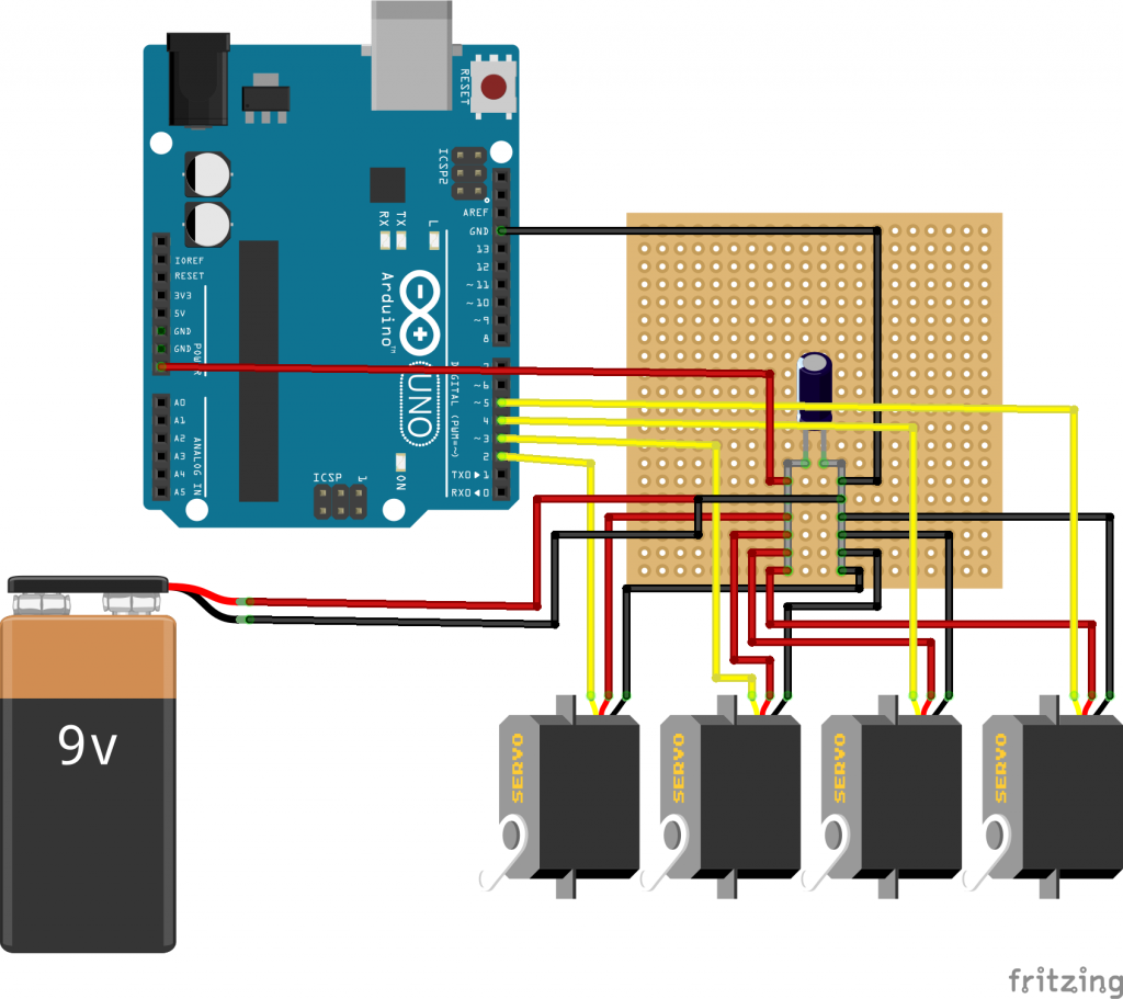
Circuit Blueprint Mark 1
I decided that my first milestone would be when I finished wiring everything together. This means that my flex sensors and servo motors, motors that turn to reach a specific point, would all be in working order, transmitting information between each other and correctly taking in power.
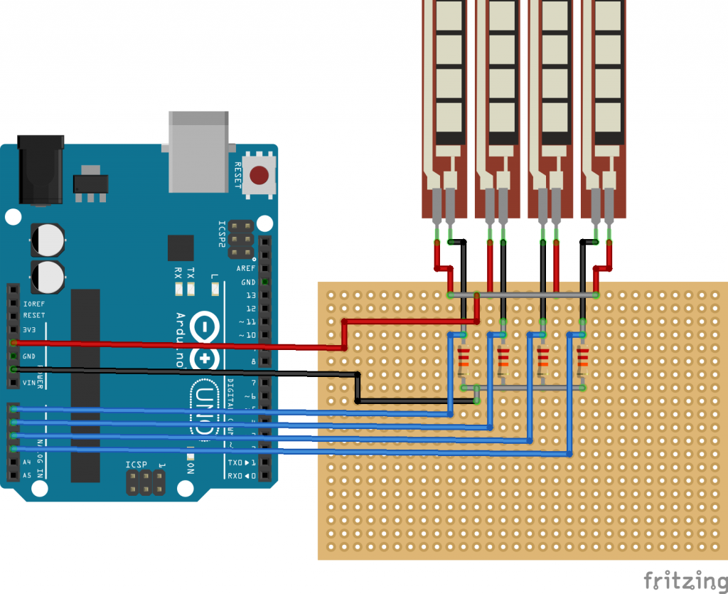
I started by wiring the breadboard connections together, as shown by the provided picture. Then, I attached the flex sensors and the Arduino to the board. The flex sensors transmit a current depending on how much they are flexed, which the Arduino converts into a number. The Arduino can do this because it is basically a combination of a miniature computer and a circuit board. It can run code and send current based on what the user needs. I use it to convert the flex sensor reading into usable data, which is then sent to the servos which are also connected to the Arduino.
The servos are connected in a different fashion compared to the flex sensors, however. Only the information wire of the servo motors is connected to the Arduino; the power cables are completely separate. The Arduinos are powered by a separate battery because the Arduino cannot supply enough voltage and power for 4 different servos. However, the servos are grounded in the Arduino, even if they do not receive power from it. The servos need to be grounded, because they will not run if they are not.
All of this allows the servo motors to turn when the flex sensors are flexed, which I will use to mimic the flexing of a human hand’s fingers with a robotic one.
Link to code:
https://github.com/ThatDesigner/Robotic-Hand-Code/blob/master/Code
Starter Project
Finished Product

Binary is another method of displaying numbers. Compared to base 10 (the normal way we count), binary, or base two, only has two numbers per digit instead of 10. For instance, 11 in base ten is 1011 in binary. While each digit of base 10 is ten to the power of the digit, in binary it is 2 to the power of the digit. 8,4,2,1 instead of 1000,100,10,1. This means that binary numbers are much bigger visually than base ten numbers when representing the same value, but binary numbers do have 1 advantage. They are used in computing because computer hardware, such as transistors, operates by either being either off or on, which is two different states. This corresponds with binary’s two different states: 1 and 0. 1 corresponds with on; 0 corresponds with off.
The Binary Blaster is a game intended to teach people binary. Upon flipping the start switch, the LED’s will display a base ten (normal) number from 1 – 15, and show the corresponding number in binary on the four buttons on the bottom. After pressing one of the buttons, the actual game will start. A base ten number will be displayed on the LED’s, but the player must press the buttons on the bottom to make a binary number that corresponds to the displayed number. If they press the correct number a different number is shown, and nothing happens for incorrect guesses. However, there is a time limit; failing it will restart the game. Finally, after getting all 15 numbers correct, the game will display the time it took to win.
The game is powered by two batteries in a series, leading to the switch. Flipping the switch connects the two sides of the circuit, giving power to the circuit board. There is also a sound switch that connects the speaker with the rest of the circuit board. The micro controller contains the code for the game, and is connected to all other pieces. The two capacitors are contained to keep the voltage stable; if the batteries give off too much, it takes it in; if the batteries give off too little, it gives off voltage. The resistor is there to reduce the current. Each button temporarily connects two sides of the circuit when pressed.