3D Printed Robotic Hand

This wirelessly-controlled, 3D printed robotic hand mimics the movements of a glove on the user’s own hand.

Engineer

Annabel Y.

Area of Interest

Bioengineering

School

UC Berkeley

Year

Freshman

Reflection

Coming into BlueStamp, I had very little engineering experience. However, at the end of this journey I have come out with a greater understanding of how to problem solve and troubleshoot as well as an insight into the kind of engineering I want to pursue. At BlueStamp, I learned to be independent; most of the problems I encountered could be solved by the internet and I learned a great deal through first-hand experience and trial and error. Blowing up servomotors and re-threading fishing line were challenges that lent themselves to reflection, re-evaluation, and modification. In addition, encountering so many different kinds of engineering sparked my interest in areas I had not entertained before. For example, computer science used to be my least favorite subject, however, the challenge of coding the wireless nRF modules became my favorite part of the project. Also, my intended major is bioengineering, but after talking to various experts in the industry, I am considering pursuing mechanical engineering and industrial design instead. Overall, BlueStamp has taught me how gloriously frustrating and difficult engineering can be, but also how incredibly rewarding it can be to struggle, persevere, and finally conquer the challenges ahead.

Below is the final presentation of my project:

You can access my code, bill of materials, and helpful links in Google Drive.

Final Milestone

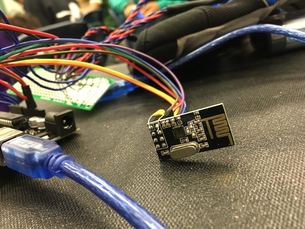
For my final milestone I implemented wireless communication between the glove and the hand using two nRF modules.
First I connect the glove and the hand each to their own arduino and nRF. I had to plug in the nRFs to particular pins on the arduino in accordance with TMRh20’s RF24 library, which I was using for coding the nrfs. I had to rewrite the original code using the functions I found in the RF24 library into two seperate codes. The glove code sends the changes in resistance from the flex sensors to the other arduino, which takes in that analog input and directs the servomotors to rotate the corresponding degree. 
One of the greatest challenges I faced was with regulating the power supply. I was supplying my servomotors with 8-8.5 volts when their max capacity was only 7.2 volts, which resulted in three servomotors blowing up. I went through three different buck converters which allowed me tune the voltage from 8 volts down to only 6 volts. However, the buck converters let very little current flow through, so they would overheat. Therefore I am currently using the battery hooked up directly to the robotic arm, but I can only use it for short periods of time so that the servomotors don’t burn out. I also soldering two capacitors to the printed circuit board that connects the battery to the servos, which store charge and help regulate the power supply.

Second Milestone

For my second milestone I connected the flex sensors to the glove and installed the servos into the hand, thereby completing the main part of my project.
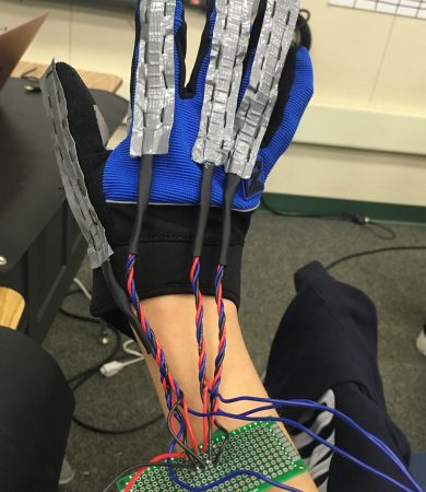
I first covered the flex sensors in duct tape and sewed them to the glove. Then I soldered a resistor and the power, ground, and analog signal wires to the flex sensors and covered them in heat shrink. After that I soldering the red power wires together onto the printed circuit board and used another wire to connect them to the 5V pin. Then I soldered the black ground wires together to the pcb and used another wire to connect them to the GND pin. Finally I plugged the blue wires into the analog pins.
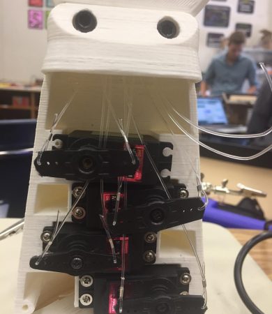
On the other printed circuit board I soldered the blue ground wires and the negative lead of the battery together, and used the yellow wire to connect the printed circuit board to the GND pin. Then I soldered the green power wires and the positive lead of the battery together. These wires are all connected to the servos which are installed in the 3-D printed robotic hand designed by Unlimited Tomorrow. Fishing line is threaded through the fingers so when the servo horns rotate, the fishing line pulls the fingers.
Most of the problems that I encountered involved the hand. The fishing line had to be constantly recalibrated and I learned that the threading should be saved for last. The servo horns were also too long so I had to use a dremel to cut the arms shorter. Finally, I the 3-D printed hand had some mechanical limitations because the fingers won’t flex very far and the thumb doesn’t flex at all, it only rotates. The servo horns don’t appear to have enough rotational power to pull the fishing wire hard enough to flex the thumb.

First Milestone

fullsizerender-9
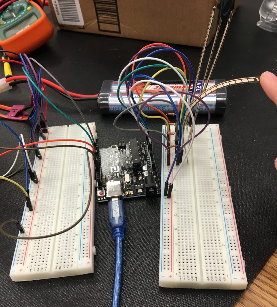
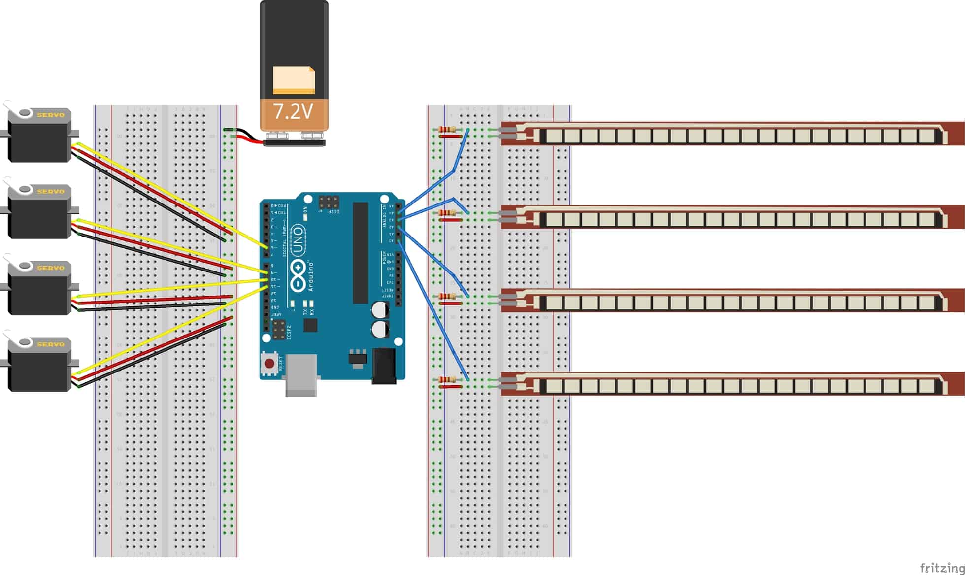
Breadboard Connections for Arduino, Servomotors, and Flex Sensors
For my first milestone I used an arduino to connect the flex sensors to the servos. The flex sensors will eventually be connected to a glove and the servos will be installed in the robotic arm. A flex sensor is like a very long resistor that increases in resistance when it’s bent. Each flex sensor is part of a voltage divider which involves applying voltage across two resistors and measuring the change in resistance between the two. The arduino detects the change in resistance through the voltage drop between the flex sensor and 22k resistor. The arduino then reads the the analog input from the flex sensor and converts that value to the servomotors’ range of 0-180 degrees. Finally, the arduino directs each servomotor to the corresponding positions.

I based my schematic off of one designed by a previous BlueStamp student.

Starter Project

My starter project is the TV-B-Gone, a universal remote control that can turn off almost any television. To turn on the TV-B-Gone you press the button that initiates the reset code programmed into the microcontroller. The microcontroller restarts the program and sends electrical signals to the transistors that act like an on/off switch for the infrared LEDs. The LEDs emit timed pulses of infrared light that are detected by the television and signal it to power off. Electrical signals are sent through various other components including two resistors, two capacitors, and an oscillator. The resistors control the flow of current, the capacitors keep the voltage stable, and the oscillator serves as an internal clock for the device.  
Through the starter project I learned how to properly solder using a soldering iron as well as learn to desolder using a wick and and a pump. I also now understand the functions of the various components of my project. Finally, I learned about how a remote control operates by sending pulses of infrared light. I did not really encounter any problems with my project other than small soldering mistakes.

Leave a Comment

Start typing and press Enter to search

Bluestamp Engineering