Hi, my name is Andrew and I am a rising senior at Monta Vista High School. I worked on the Minty Boost as my starter project, and a USB charger as my main project. The Minty Boost takes the voltage supplied by two 1.5V batteries and steps up the voltage to 5V in order to charge your phone. My USB charger converts both mechanical and solar energy into electrical energy. The user can generate electricity by turning a crank, which is converted to a lower voltage to charge a phone. The solar panel generates energy that a power regulating module makes it usable by a phone to charge. Blue Stamp was a great experience to apply what I learned in my physics class this year to something tangible. Overall, I learned a lot of valuable skills such as troubleshooting as well as a lot of factual knowledge such as how circuits, switches, and solar panels work.
Main Project: Hand Cranked USB Charger
Designs:
Final Milestone:
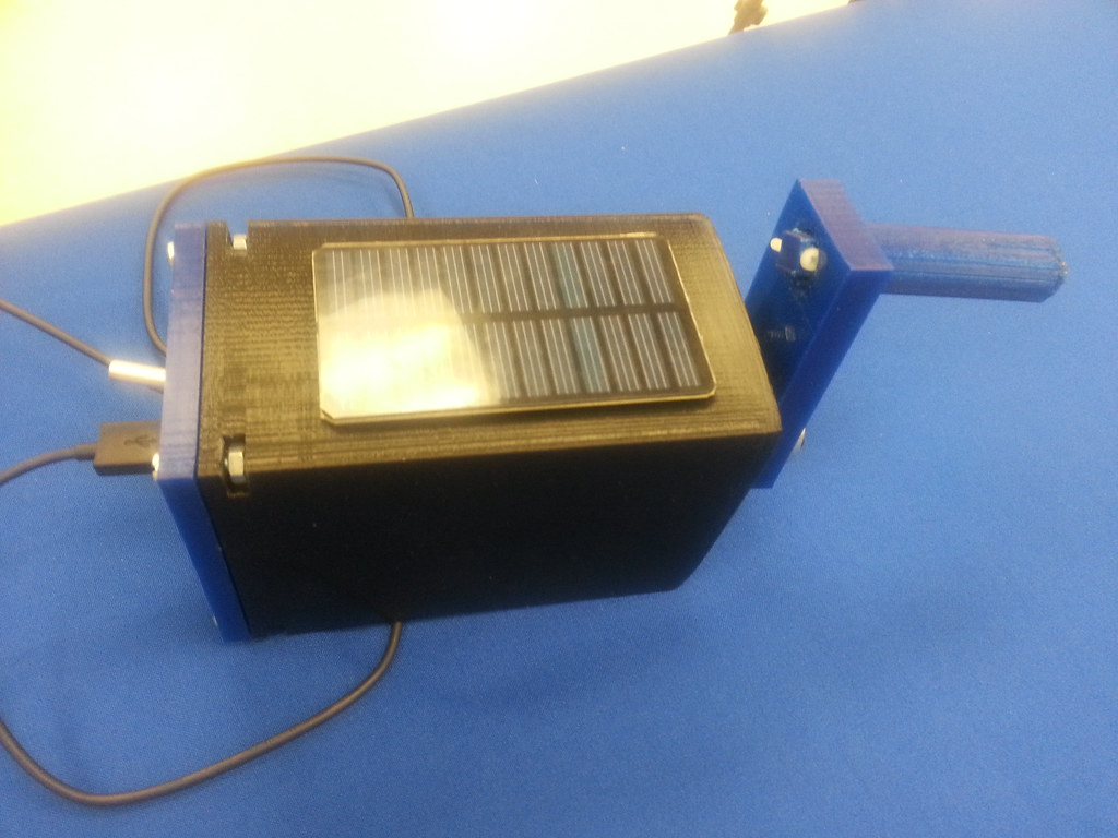
For this last milestone, I decided to integrate a solar charging option with my crank USB charger. I achieved this using a 6V 0.5 W solar panel and connected this to a voltage regulating circuit. The voltage produced by the solar panel depends on the intensity of the sunlight. Depending on the voltage produced, the voltage is either stepped up or stepped down to around 5V. This output voltage is connected to a switch, which controls which type of charging the user would like. One problem with the circuit is that the solar panel produces a small current, and this could be solved by adding solar panels in parallel to increase the current. In addition, the voltage regulating module does not work for voltages below 3V, and as a result, the intensity of the sunlight needs to be above a certain threshold for the charging to be achieved. This can be prevented in the future by using a module that functions with a lower input voltage. From this milestone, I learned about how solar panels and switches work, and specifically how to wire them into a circuit.

Milestone 2:
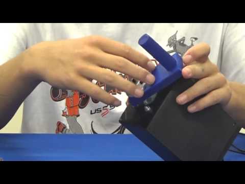
For this milestone, I decided to make my hand cranked charger more efficient, while also providing and enclosure that would hold and protect the circuit. I achieved this through creating 3D designs using Autodesk’s Inventor 3D modeling program. Creating these designs were more difficult than I thought they would be, since I had never created 3D designs using programs before. In addition, I had to have precise measurements for the placement of each part of the circuit as well as for the placement of screws to hold everything in place. One challenge was figuring out how to secure the screws in place, since the plastic used to print out the designs was not strong enough to provide a foundation for threads for the screws. I ended up including many slots for nuts in order to secure the screws in place. In addition, my initial crank design failed due to the metal shaft of my motor biting into the plastic of the crank. As a result, I had to incorporate the metal wheel hub of my original crank into my new design that included a handle. From my experiences, I learned how to use Inventor and how 3D printing works.
Milestone 1:
For my main project, I decided to build a hand cranked charger. This project converts mechanical energy provided by the user and converts it into electrical energy, using a motor and a step down transformer. This is achieved through cranking a 12V DC motor, creating a current and voltage that needs to be converted to a usable voltage by the phone being charged. There is a diode attached to the motor to protect the circuit from reverse current if the motor is spun in the opposite direction. In the circuit, there are a couple of components. The inductor stores energy and helps stabilize the current, while capacitors store energy and stabilize the voltage. The input voltage from the motor is reduced to a lower voltage using a step down transformer, and the output voltage can be adjusted using a potentiometer, which allows the user to control the resistance of the circuit. The output is 5v and a current around 550 mah . During this project, I came across many problems. The initial problem was due to my motor having faulty soldering, and as a result, it needed to be fixed. However, the motor further caused problems and had to be replaced. After the new motor arrived, I discovered I had a short in my circuit board, and I needed to replace it. After fixing these problems, I discovered that having my phone plugged in further increased the resistance of the circuit, making charging difficult by making the crank harder to turn, creating a lower voltage than is needed. As a result, I decided to switch back to my old motor, which still worked, due to it working at a higher RPM and being easier to turn. In addition, I decided to work on a more efficient hand crank attached to the motor to provide a more steady current. In addition, my major problem that took the majority of the time to solve was that some solder connecting the positive output from the IC to the positive terminal of the USB connector touched the outer metal portion of the connector, which is ground. After noticing this small mistake, the circuit worker.
Starter Project: MintyBoost v3.0
For my starter project, I built the MintyBoost. This project takes the 3.0V input provided by the batteries and converts it to an output of 5.0V which is usable by devices such as phones. This project is composed of a few main components: diodes, resistors, capacitors, inductors, power supply, and boost converters. All of the parts came in the kit, but knowing their functions was important. As a result, most of the work necessary to complete the project involved soldering, which was not that difficult since I had done it before. The most difficult part of the starter project was identifying the direction of the current and identifying the polarity of each component of the circuit.