
My name is Andrew and I am 15 years old. I attend Columbia Secondary and I’m a rising sophomore. This year in Bluestamp I created a portable charger for my starter project and a laser security system for my main project. By completing my starter project I learned many of the basic skills needed to complete any project I want. I learned how to solder wires to a PCB and how to de-solder as well. After about spending three days on my starter project I finished it and I actually use it to charge my phone during the day.While building my main project, I encountered many challenges and problems and learned a lot from completing this project. I mainly learned a lot about coding using an arduino and about the arduino it self which I found interesting because I want to become a programmer. Overall, I had a great and fun experience at Bluestamp and I really enjoyed building both projects.
Laser Security System

Final Milestone
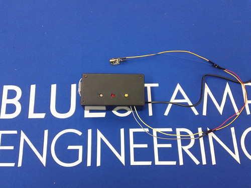
To set up the security system, plug it in to the wall and aim the laser so that it is pointed at the photo resistor. The laser will keep the amount of resistance of the photo resistor over the amount needed to keep the alarm from not going off. When someone breaks the laser beam, the alarm off because the value went below the set amount because the person is blocking the photo resistor from receiving light. Even if the person who tripped the alarm tries to aim the laser back at the photo resistor, the alarm will still go off because the only thing that can stop the alarm is the passcode. You can even try guessing the password as many times as you want but it wont stop the alarm. When the correct passcode is entered the alarm will stop and to restart the system you would press the * button on the keypad. There will be a 15 second delay so that you can aim the laser at the photo resistor while the alarm doesn’t go off.
Some of the difficulties I had in this project as a whole were mainly the code. I had trouble with writing code to make sure that after you trip the laser beam that you cant just aim the laser back and that the alarm will turn off. I first tried using two separate if statements saying if the amount of resistance of the photo resistor is higher than 650 the alarm doesn’t go off, but if it is lower than 650 the alarm goes off. The problem with this is that if you aim the laser back on the photo resistor the alarm will turn off without putting in the passcode, which is not supposed to happen. My second attempt I used a Boolean statement. I created a variable called alarm, which is set to 0. The alarm doesn’t go off only when that variable is 0. When the laser is tripped, the variable, alarm, gets set to 1, so aiming the laser at the photo resistor will not work anymore. The only way to set alarm back to 0 you have to put the correct passcode in. this fixed my problem that I was having.
Schematic:
Click here to view bill of materials
Second Milestone
For the second part of my project I connected the keypad to my arduino and wrote the code for the passcode. To connect my keypad I first had to download the code that made the arduino able to detect that a key was pressed and then print that number that was pressed. The next part would be connecting the pins of the keypad on the arduino in the right order or the arduino will print the wrong number or no number at all. After I finally got the right order I made sure that the arduino printed the right numbers so I pressed all the keys in order and it worked.
Now the tricky part which is writing the code for the passcode. In my code the four variables all start out as the same character, which would be an equal sign in my code. Once you punch a key one of the four variables value gets replaced with that number, however how will the arduino know when a variable already has a number assigned to it and when to move on to the next variable. Well, my code does both. My code starts from the last variable, number4, and goes down to the first variable, number, checking each time if the variables below it already have a value and if they do, then that variable gets that value, but if they don’t it goes down to the next variable and does the same system of checking until there is a variable without a value.
if (number != ‘=’ && number2 != ‘=’ && number3 != ‘=’ && number4 == ‘=’ ){
number4 = key;
}
if (number != ‘=’ && number2 != ‘=’ && number3 == ‘=’ ){
number3 = key;
}
This is an example from my code. As you see it starts backward from number4 down to number1. It first checks if the variables before number4 already have a different value than ‘=’. If they all do then it checks if the variable itself doesn’t have a different value than ‘=’ and if it does than the arduino will print if the passcode is correct or to reset the code by pressing the * key on the keypad.
First milestone
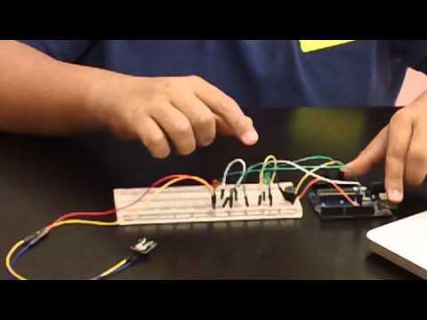
For the first part of my main project I made the alarm. Basically if you trip the laser the alarm will go off. How it works is that the photo resistor sends different values of resistance, depending on the amount of light it receives from 0 to 1025, to the Arduino. When the Arduino receives this data, it sends out that value to the output pins I set for the green led, red led, and the buzzer and depending on the value the alarm will go off or not. Lighting from a room hitting the photo resistor gives a value of about 800 to 900 and the laser directly pointed at the photo resister is a value of 1,023. When I tripped the laser to see the range of values I got between 650 and 700, so I made the cut off number 750. When the laser is pointed at the photo resistor, the green LED is on meaning nobody tripped the laser, but when someone trips the laser the red LED turns on and the buzzer goes off.
The major difficulty I had during this part of my project were writing code for the arduino. I have never worked with an Arduino before so I had difficulty understanding it as well as finding what I specifically needed for my alarm. I spent two days looking through numerous examples to understand the different parts for my alarm. For example, I learned how to make an LED turn on and how to use Boolean statements for the switch between the green LED turning on to the red LED and the buzzer turning on when the laser is not pointed at the photo resistor. Then it took me a day to actually write the code and since I was new to writing code I went step by step to make sure I got everything working which in the end, it finally did.
Starter Project
For my first starter project I built a mini boost which is a portable charger that uses two AA batteries to charge your favorite accessories like an iPhone. The kit included a circuit board, resistors, a boost converter, power conductors, battery holder, a USB jack, and ceramic capacitors.
In doing this project, I learned how to solder pieces of metal together, disorder, and how to use a multimeter to measure volts. On the first day, I learned the hard way that the soldering iron needs to be clean in order to melt the solder. I struggled to connect one resistor for about an hour until I realized that the problem was that the solder iron wasn’t clean. When I switch my solder iron to a clean one, I didn’t have any more trouble soldering. After fixing my problem I finished connecting everything to the circuit bored and tested my charger. In my fist attempt my charger didn’t work. I found out that I put the boost converter backwards on my circuit board and this didn’t allow the charger to work. After I flipped the boost converter and tried to charge an iPhone it worked.
After completing this project I feel more confident in my skills with soldering and my understanding of circuits. How my project works is that the electrons from the AA batteries flow though the different types of resistors in the circuit which limit the amount of electricity flowing through the circuit. Then the electricity flows into the capacitors. One of the capacitors help the boost converter generate the right amount of voltage while the other capacitor stabilizes the output voltage. Then, the boost converter produces the electricity in a greater voltage to the USB to charge the accessory.