
Hey guys! My name is Alex Z and I go to Mills High School. I’m currently a sophomore and will be a junior next year. My starter project is the Minty boost and my main project is the S.M.A.R.T. alarm clock and LED Binary Clock. Hope you enjoy! 🙂
Main Project #1(LED Binary Clock)


Final Video and Presentation Night video
Reflection: Wow! I finally finished my LED Binary Clock! Not only was this project a challenge, it was also a great experience that taught me a lot more about engineering. I learned many skills such as using new tools (the CNC machine), learned simple code, and how many cool parts worked, such as an Arduino Uno and a bread board. One addition that I added to my LED Binary clock was that I drilled two holes on sides of the wood case, which allowed for me to put a thin copper wire for me to hang my clock. Another addition I made to the LED Binary clock was making a number one, two, four, and eight using a CNC machine.
Project challenges: Some challenges that I faced that were pretty difficult was the soldering, wiring, cutting the wood for the case, and one of the digital pins not working. First off, the soldering was really time consuming. I spent about two days soldering the wires and LEDs together. Secondly, the wires always got tangled and kept on getting in the way of pressing the buttons that would change the clock’s time. The third problem or challenge that I faced was cutting the wood. I measured the wood a little bit off, leading to small gaps in my LED Binary clock case. Lastly, the problem that caused the most issues was that my Arduino Uno’s digital pin four did not work. So, I had to change my code so that I could use a different pin on the Arduino Uno instead.
Milestone #2
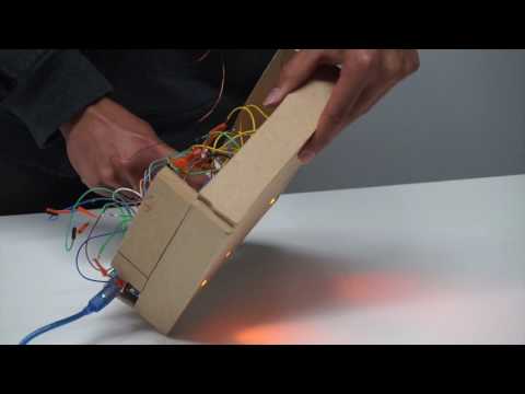
My second milestone was to make a wood case for my binary clock. This made it so that the LEDs and wires would not get tangled if they were hot glued in place. To do this, I carefully measured and cut the necessary pieces. I wanted a simple square shape which made it easy for me to cut the wood. The second step that I did was to drill holes into the wood, making it so that my LEDS could fit through the holes. The holes allowed the LEDs to show and shine, but did not show any wires or my Arduino Uno. Then, I hot glued the parts together to form a square. The measurements of my binary clock are 7 ½ by 7 ½ inches. Originally, I thought of building a bigger size case, but I realized that I didn’t have enough wood so I decided to make the size smaller. Afterwards, I used sandpaper to make my case more smooth.
code:
int second=0, minute=0, hour=0; //start the time on 00:00:00
int munit = 0;
int hunit = 0;
int valm=0;
int valh=0;
int ledstats = 0;
int i= 0;
boolean light = 1;
void setup() { //set outputs and inputs
pinMode(1, OUTPUT);pinMode(2, OUTPUT);pinMode(3, OUTPUT);pinMode(18, OUTPUT);pinMode(5, OUTPUT);
pinMode(6, OUTPUT);pinMode(7, OUTPUT);pinMode(8, OUTPUT);pinMode(9, OUTPUT);pinMode(10, OUTPUT);
pinMode(11, OUTPUT);pinMode(12, OUTPUT);pinMode(13, OUTPUT);
pinMode(14, INPUT);
pinMode(15, INPUT);
pinMode(16, INPUT);
digitalWrite(14, HIGH);
digitalWrite(15, HIGH);
digitalWrite(16, HIGH);
}
void loop() {
static unsigned long lastTick = 0; // set up a local variable to hold the last time we moved forward one second
// (static variables are initialized once and keep their values between function calls)
// move forward one second every 1000 milliseconds
if (millis() – lastTick >= 1000) {
lastTick = millis();
second++;
}
// move forward one minute every 60 seconds
if (second >= 60) {
minute++;
second = 0; // reset seconds to zero
}
// move forward one hour every 60 minutes
if (minute >=60) {
hour++;
minute = 0; // reset minutes to zero
}
if (hour >=24) {
hour=0;
minute = 0; // reset minutes to zero
}
munit = minute%10; //sets the variable munit and hunit for the unit digits
hunit = hour%10;
ledstats = digitalRead(16); // read input value, for setting leds off, but keeping count
if (ledstats == LOW){
light=!light;
delay(250);
}
if(light== LOW){
for(i=1;i<=13;i++){
digitalWrite(i, HIGH);}
} else {
//minutes units
if(munit == 1 || munit == 3 || munit == 5 || munit == 7 || munit == 9) { digitalWrite(1, LOW);} else { digitalWrite(1, HIGH);}
if(munit == 2 || munit == 3 || munit == 6 || munit == 7) {digitalWrite(2, LOW);} else {digitalWrite(2,HIGH);}
if(munit == 4 || munit == 5 || munit == 6 || munit == 7) {digitalWrite(3, LOW);} else {digitalWrite(3,HIGH);}
if(munit == 8 || munit == 9) {digitalWrite(18, LOW);} else {digitalWrite(18,HIGH);}
//minutes
if((minute >= 10 && minute < 20) || (minute >= 30 && minute < 40) || (minute >= 50 && minute < 60)) {digitalWrite(5, LOW);} else {digitalWrite(5,HIGH);}
if(minute >= 20 && minute < 40) {digitalWrite(6, LOW);} else {digitalWrite(6,HIGH);}
if(minute >= 40 && minute < 60) {digitalWrite(7, LOW);} else {digitalWrite(7,HIGH);}
//hour units
if(hunit == 1 || hunit == 3 || hunit == 5 || hunit == 7 || hunit == 9) {digitalWrite(8, LOW);} else {digitalWrite(8,HIGH);}
if(hunit == 2 || hunit == 3 || hunit == 6 || hunit == 7) {digitalWrite(9, LOW);} else {digitalWrite(9,HIGH);}
if(hunit == 4 || hunit == 5 || hunit == 6 || hunit == 7) {digitalWrite(10, LOW);} else {digitalWrite(10,HIGH);}
if(hunit == 8 || hunit == 9) {digitalWrite(11, LOW);} else {digitalWrite(11,HIGH);}
//hour
if(hour >= 10 && hour < 20) {digitalWrite(12, LOW);} else {digitalWrite(12,HIGH);}
if(hour >= 20 && hour < 24) {digitalWrite(13, LOW);} else {digitalWrite(13,HIGH);}
}
valm = digitalRead(14); // add one minute when pressed
if(valm== LOW) {
minute++;
second=0;
delay(250);
}
valh = digitalRead(15); // add one hour when pressed
if(valh==LOW) {
hour++;
second=0;
delay(250);
}
}
Milestone #1
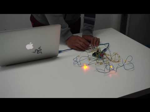
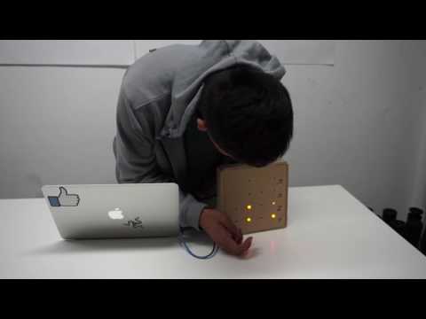
For my milestone #1, I wanted to make it so that the LEDs could shine and be bright enough that I could see the lights far away. In addition, I wanted to add three buttons, connecting to my Arduino Uno. The three buttons control different things on the clock. The first button connects to the Analog zero, the second connects to Analog four, and the last button connects to Analog five. To do this, I used a breadboard, wires, and resistors. To insulate the electrical wires, I put tape on my resistors. I then used the code to make the LED light up. It took me tons of wire and a lot of soldering to connect everything together. At first, I thought I had messed up when I uploaded the code. But, I found that I was suppose to put the wires at 5V instead of GND. This milestone in general was somewhat difficult because it took forever to solder all the wires, LEDs, and resistors. During this milestone, I learned a lot more about how to use breadboard, what electrical tape is used for, and more knowledge about LEDs.
Guide to build your own and code for the LED Binary Clock

Schematics for LED binary clock.
How the LED binary clock works: The LED binary clock is simple and also simply awesome. Before I explain how it works, you need to make sure everything is placed correctly for the LEDs to display correctly. This means, you need to double check your soldering for connecting your resistors, LEDs, wires, and female female jumper wires. First off, you need the right code for my binary clock and then upload it to my Arduino Uno. Once uploaded, depending on how you connected your LEDs to your digital pins, different LEDs will light up. You would then need to figure out where to place each LED to give off the correct time. This is because each LED is placed in a different digital pin gives off light at different times. You then move the LEDs into there right spot in the case so that the LEDs give off the correct time. This is how the LED binary clock works.
| Parts |
|---|
| Arduino Uno |
| 3 push buttons (to change the time) |
| A lot of wires |
| Electrical Tape |
| 13 LEDs |
| MDF wood (used for the case) |
| 16 resistors ( I used yellow LEDs) |
| Female Female header |
| Breadboard |
Bill of materials link to check cost of project
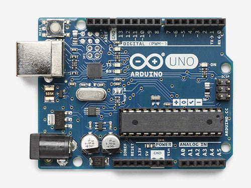
Arduino Uno (what I used for my Binary clock)
Milestone#3
For my third milestone, I wanted to test if my wiring for my pervious milestone could also work for touch screen on my TFT touch screen. However, this was unsuccessful so I had to add a addition female female jumper wire and tweaks to another example code. I used a different example code this time so that I could test my touch screen and my image display. With this code, I could tell where my finger was touching on the TFT touch shield and how hard you were touching it. Using software called particle dev, I could see the x and y coordinates of my finger.
Milestone#2
For my second milestone, I wanted to test if my wiring to my photon was correct by using some example code. This is because I was not using the Arduino Yun anymore and thus, I had to search up how to connect the TFT touch shield to my Photon. I eventually found some help on the Photon community that really helped me figure out the correct Pinout for the Photon and TFT touch shield. Finding the correct pinout was quite difficult because there were two versions of the TFT touch shield 2.8”. Version two and Version one were different. In addition, another step that I found difficult was finding the pinout from trial and error. Eventually I got the right pinout and my TFT touch shield displayed images and words. If I was still using the Arduino Yun, I would not have to wonder about the wiring. This is because the Arduino Yun and the TFT touch shield can be easily put together.
Display Pinout
Photon TFT touch shield
A2 D10
A3 D13
A4 D12
A5 D11
TX D7
GND GND
Vin 5V
D4 D9
D5 Reset pin

Photon

TFT touch shield
Why I decided to switch from using a Arduino Yun to a Photon on my main project: Originally, I had wanted to use the Arduino Yun for my S.M.A.R.T. alarm clock instead of my Photon. I even had the code ready for the Arduino Yun. However, I ran into many errors when I tried to use the Arduino Yun. The main error that was hard for me was that I could not connect to the Arduino Yun’s wifi. I tried to reset my Arduino Yun to the factory setup but was unsuccessful after many attempts. I then tried many guides online to fix my Arduino Yun so that I could connect to my Arduino Yun’s wifi. If I could not connect to the wifi, I could not send the code to the Arduino Yun via wifi and make the S.M.A.R.T. alarm clock function. Another step that I tried was to upgrade my Yun from U-boot. Again, my Arduino Yun did not have a wifi signal that my computer could connect to. If it could, I would have been able to create the S.M.A.R.T. alarm clock using the Arduino Yun. Unfortunately, after wasting a week I decided to use a photon to create the S.M.A.R.T. alarm clock.
How the S.M.A.R.T. alarm clock works with the Photon: With the Photon, the S.M.A.R.T. alarm clock works about the same. The photon basically replaces the Arduino Yun and does everything that Yun was suppose to do but I could not figure out how. Thus, I use the photon to upload the code via wifi which then displays the TFT touch shield display and touch screen.
Milestone #1
My first milestone to my S.M.A.R.T. alarm clock was to put all the parts together. These parts included getting my TFT touchscreen shield, Arduino Yun, my SD card, and my speaker all together. Theses four parts need to work in order to make the S.M.A.R.T. alarm clock function correctly. The second part of my milestone was to download the Arduino software onto my computer. In addition, I imported the two libraries into my Arduino called the TFT Touch Shield V1 and the Touch Screen library. Some challenges that I faced were finding the four parts online that I needed for the clock at a cheap price. Another challenge I faced was learning how to import my files into the library of the Arduino software.
Guide on building the S.M.A.R.T alarm clock
How the S.M.A.R.T. alarm clock works: The S.M.A.R.T. alarm clock with the four parts of the alarm clock consists of the USB speaker, TFT touchscreen, Arduino shield, microSD card, and the Arduino Yun. The Arduino Yun has two processors, one that runs the embedded version of Linux and is used to connect to the internet over wifi or Ethernet called the Atheros AR9331. The second processor is used to connect to the Atheros Ar9331 and is the processor called ATmega32u4. For the S.M.A.R.T. alarm clock, it uses the Temboo service to connect with my personal google mail and calendar. The USB speaker is used to play the music to wake you up to in the morning. The TFT touch screen is to display the time and the clock. In addition, the touch screen is needed so that you could touch the shield in order to silence the alarm. Finally, the microSD is used to store the data to upload the display on the touch screen. I would use my Arduino which is connected to the wifi and upload the sketch to my Arduino Yun. After that, the code makes the amazing alarm clock when all the parts are put together. I then set up the google calendar and input the time a meeting that I have will be. The alarm will automatically set itself one hour from the earliest meeting. The alarm clock by default will only look at meeting before noon so if there is a meeting after noon, the clock will not set itself. Finally, when it is time, the alarm will play a loud noise to wake me up. Another way the alarm clock can wake me up is using gmail. When someone sends a email to you saying “WAKE UP”, the alarm clock will go off.
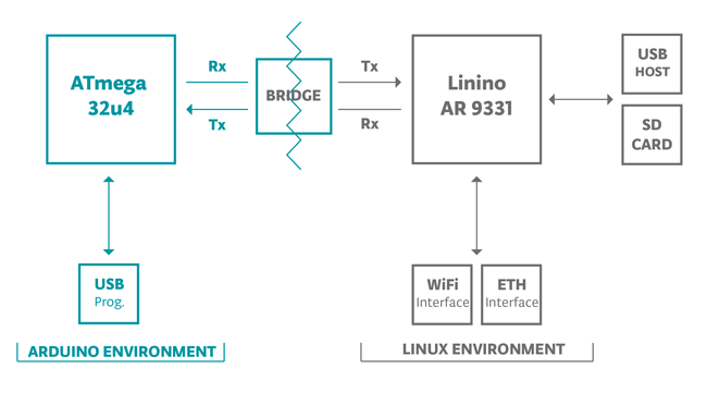
Picture of how the two processors work together in the Arduino Yun.
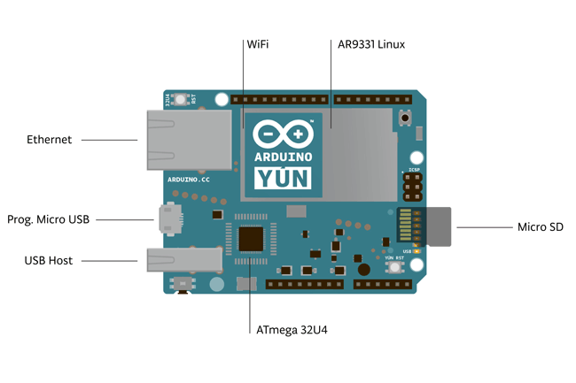
Picture of the main parts of the Arduino Yun by Arduino.cc
Documentation for Starter Project (Minty boost)
How it works: To start off, the Minty boost is a device using two AA batteries to charge any camera, iphone, mp3 player, and other devices that can plug into a USB port to charge. The Minty Boost uses the two AA batteries as a power source that provides 3 volts. The IC1 is the boost converter chip that boosts the voltage to 5 volts instead of 3 from the two AA batteries. The four capacitors help smooth the output voltages. The 5 resistors drop voltage throughout the circuit. The schottky diode D1 makes sure that the battery charges the phone and not the other way around. Finally, the power inductor L1 is used to convert from low to high voltage.
Buy and build your own Minty Boost
Challenges I faced: Some challenges that I faced included desoldering, how to solder correctly, and figuring out how the starter projected worked. First off, I was never taught any of these things before BlueStamp, so I learned from trial and error. Many times I failed to solder correctly, including not soldering in the correct place. For example, I soldered the USB port into the wrong place and in turn, I had to desolder it. Desoldering was also new to me and I learned to move the parts I soldered incorrectly to the right places. This was very frustrating and it took more time trying to desolder than doing anything else in the project. I regret that I made mistakes placing my parts on the minty boost the wrong way which in turned wasted a lot of time. Lastly, another challenge that I faced was learning why the starter project worked. I took me awhile to figure this out, but once I learned why, I understood how the device worked.
What I learned: I learned how to solder and desolder. For example, I learned how to solder parts to the charger circuit. Desoldering many parts that I put in wrong took time and patience. In addition, I learned the parts of the Minty boost and how the Minty boost works together with all the parts.
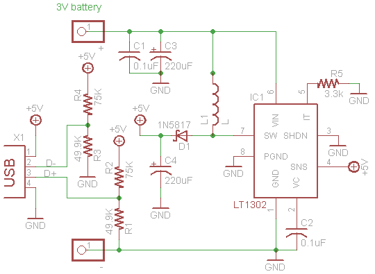
Schematics for my starter project by adafruit