Hi everyone, welcome to my page! My name is Alex and I am part of the class of 2016 at Leland High School. My starter project is the Exploding Star Organ and my main project is the RC Hovercraft, a new project this year.
I entered this program and chose my project in order to gain hands-on experience with mechanical and electrical engineering, since I already had some experience in programming beforehand. Throughout the program, I faced challenges in mechanical design and electrical systems--how I could design a hovercraft that would be balanced and could be lifted by a single motor, as well as difficulties getting the electronics to work properly. Through working with lots of frustration, I learned a lot about engineering, such as the importance of patience, as well as how much every detail matters--though it may seem obvious when mentioned, if the smallest part is off, the whole will not work, and in the case of electronics, might result in sparks or an explosion.
Main Project: RC Hovercraft
Link to the individual parts of the hovercraft shell:
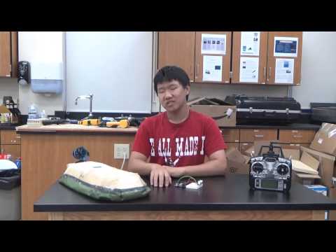
Final Recording and Next Steps
This is the final recording for my project. At this point, I have a working hovercraft with no significant operational problems. My next steps after Bluestamp are to add autopilot to the hovercraft by integrating an ultrasonic sensor, as well as an Arduino, into the hovercraft. There are some difficulties in connecting the Arduino to the RC receiver as well as the other electronics without taking up too many slots of the receiver as well as ensuring that everything receives power, which have been the main problem in integrating an autopilot. The ideal final product would be a hovercraft that can switch between autopilot and RC at the flick of a switch on the controller, which is something I will continue to work on past Bluestamp. I thoroughly enjoyed my experience here and am grateful for everything I learned, and will bring this experience to further developments on this hovercraft and other engineering-related endeavors in the future.
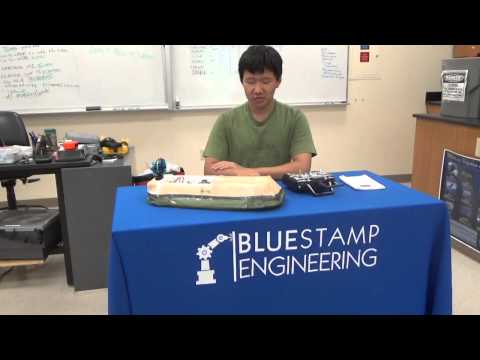
Milestone 2: Assembly Completed
At this stage, I finished putting the electronics into the shell (modifying it during the process) and finished covering the necessary parts of the shell in fiberglass (after inserting the electronics). The hovercraft is more or less finished at this point; after electronics were inserted (particularly the servo in the back), I put on the last of the fiberglass covering for the hovercraft, sealing the servo and its wiring into the back slot of the hovercraft. Upon testing it, I found that the hovercraft was tilting to one side when the skirt was inflated, and after further examination and creating a centered slot for the battery in the inside of the craft, I found that the likely cause of the tilting was that the servo in the back not being centered (in order for the mounted motor to be centered, the servo has to be off-center). A solution was found in adding weight to the other side of the craft, in this case, in the form of a used AA battery, duct taped to the inside of the craft. In this stage, I also organized the electronics inside the craft a bit, taping some of the wires together so the inside is recognizable instead of a mess of wires.
After balancing the hovercraft (though it still drifted a bit), there were still a few operational difficulties. Though the new battery is a lot better than the old ones, it is still impossible for it to run both motors at full throttle at the same time. Even using both motors at a medium high level throttle will cause one to stop working, presumably because of insufficient current (it is split between the two motors). After testing, I found a good level to keep the lift throttle at which allowed the thrust motor to operate at high throttle. As a side note, powering the thrust motor while the lift motor is active reduces the power output of the lift motor, as expected. As another side note, steering this thing is exceptionally hard.
Milestone 1: Electronics + Shell Completed
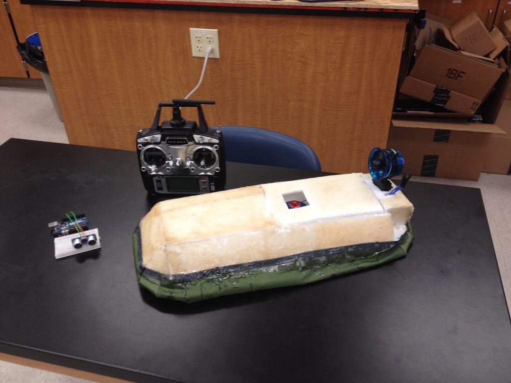
For the RC Hovercraft, the first step was to design the shell. The base is made of thin styrofoam, glued together and all covered with fiberglass, attached by using Bond-o. There is a thin second layer at the bottom of the hovercraft, which allows air to be pushed to the sides into the skirt by the lift motor. The skirt is made of tent fabric, cut and then sewn together; it is meant to inflate and be the only part of the hovercraft that touches the ground. The hovercraft also has a lid on the top so electronics can be inserted and modified easily.
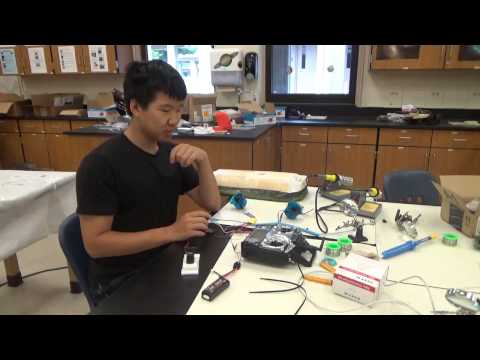
The electronics came with their own difficulties. The batteries I initially worked with weren’t strong enough, each only providing 3.7 volts. Even after connecting the batteries in series to double the total voltage, the current was still very weak at about .5 amps, which was not increased by connecting the batteries. The Electronic Speed Controllers (ESCs) also presented a lot of difficulty, especially since they didn’t come with any instructions, so getting them to work required a lot of research online for similar ESC manuals, as well as a lot of experimenting with them. We eventually found solutions for these problems: after testing the ESCs and motors with a power supply, a new battery (a single 7.4 volt battery this time) and programming the maximum and minimum throttle on the controller every time the motors are turned on. The startup process was made a lot easier by inserting a switch into the circuit (plugging in a battery while holding up a switch on the controller is not easy). The motors both work at this point, as demonstrated in the video.
Starter Project: Exploding Star Organ
This starter project utilizes a microphone that sends out electrical signals when it receives an input. These signals are then amplified by transistors and passed through two IC circuits, one of which outputs a series of clock pulses. These pulses are processed by the smaller IC circuit, which sends signals to transistors connected to the LEDs. These signals power the LEDs, lighting them up in rings. Four capacitors block direct current while allowing alternating current to pass through. The current in the circuit is controlled by 11 resistors as well as two trimmer resistors, which can be adjusted to change the sensitivity of the microphone.