
______  _      _   _  _____  _____  _____   ___  ___  _________
| ___ \| |    | | | ||  ___|/  ___||_   _| / _ \ |  \/  || ___ \
| |_/ /| |    | | | || |__  \ `--.   | |  / /_\ \| .  . || |_/ /
| ___ \| |    | | | ||  __|  `--. \  | |  |  _  || |\/| ||  __/
| |_/ /| |____| |_| || |___ /\__/ /  | |  | | | || |  | || |
\____/ \_____/ \___/ \____/ \____/   \_/  \_| |_/\_|  |_/\_|
Introduction
Hello! My name is Alex, and I’m currently attending the Urban School of San Francisco. I’ve always loved building and being creative, but I never tried coding and robotics. Bluestamp has given me an excellent chance to expand my knowledge on these subjects.
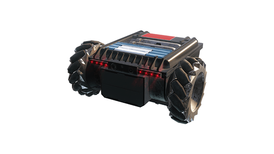
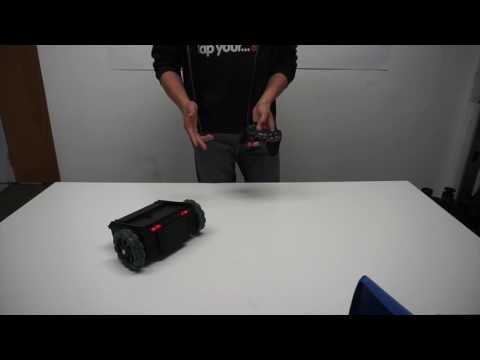
My main project is a variation on an RC tank, which is remote controlled using a wireless PlayStation 2 controller. This is what the chassis of the bot is supposed to look like:

I, however, wanted to challenge myself with 3d modeling as well, and chose to redesign my RC tank to fit a case of this design:
To make it work, I needed to redesign the chassis and make my own 3d printed case.
Reflection
I came to BlueStamp knowing very little about electronics, robotics, and 3d modeling. After only 6 weeks, I know much so much more than I even thought I would. I’ve been seriously considering engineering as a career path, but I’ve never had that much experience with its different branches. BlueStamp was the perfect opportunity to learn more about both engineering and my interests.
Custom RC Robot Tank

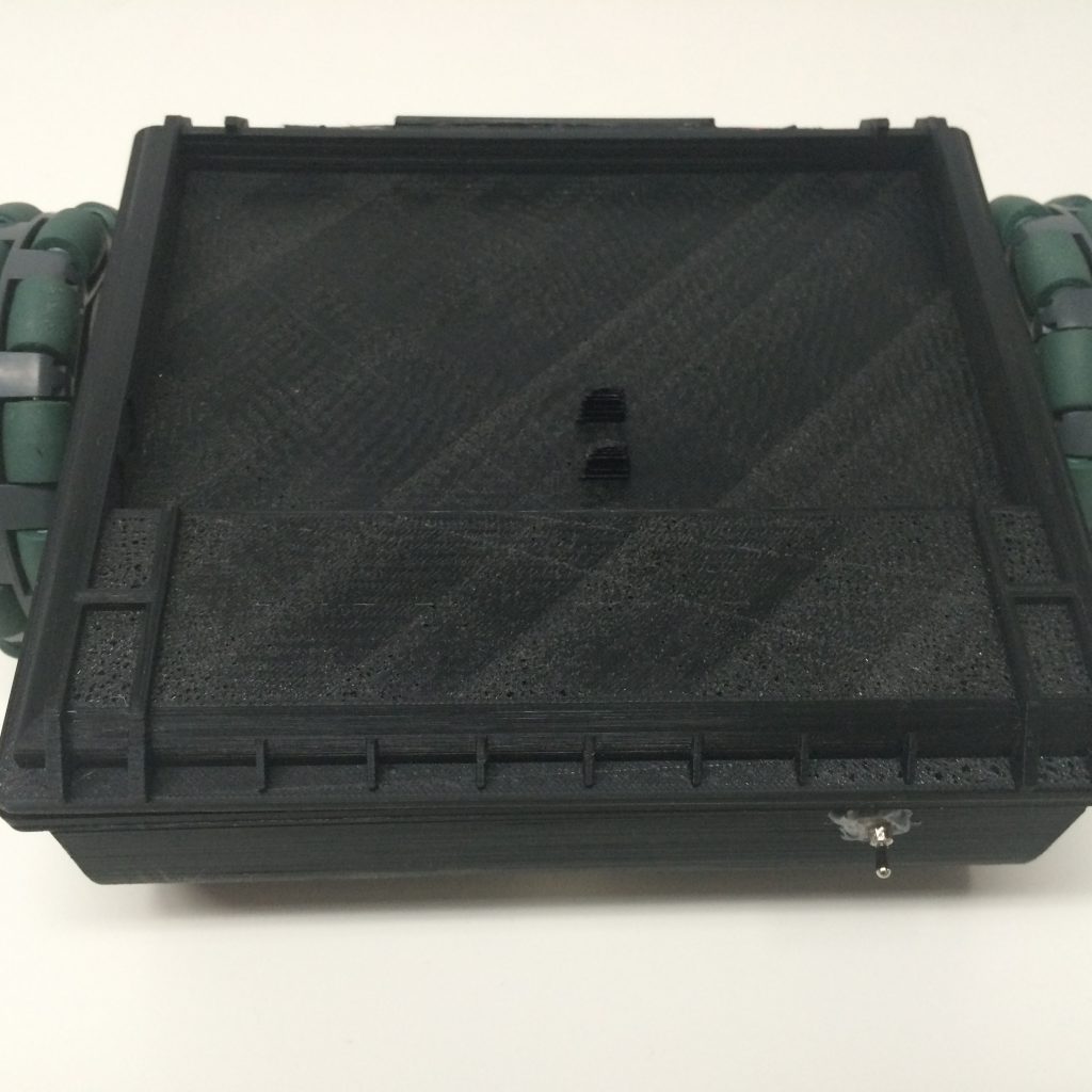
-

- The front of the case, complete with 8 lit LEDs.
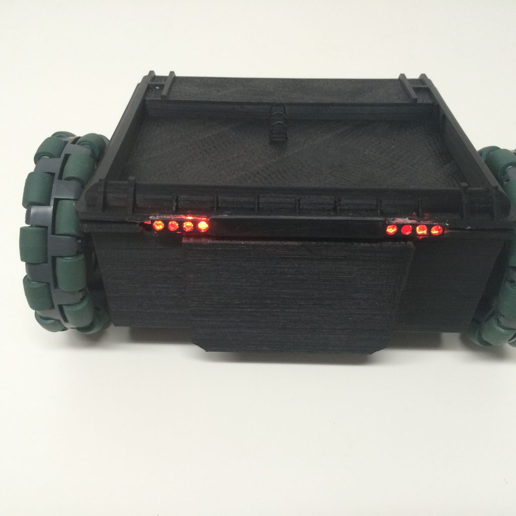
-
- The back of the case, with a small hole in the back to fit the power switch.
My finished product is a wirelessly controlled RC car. It features a 3d printed case that I personally designed to match the above image (more on that in the section below). The RC Tank Mk.2 is controlled using a wireless PlayStation 2 controller, which is useful because each signal output on the receiver is divided into separate pins that are easy to hook up to an Arduino. It has entirely custom code based on the PS2X library and the Adafruit motor shield library for Arduino. An Arduino library is a set of code that is used to detect and recognize things like motors and controllers, as well as adding custom commands and variables. This allowed my code to detect inputs from the PS2 controller and power my motors. Finally, My RC tank features 8 LEDs and a small speaker to make it more accurate to the ingame model.

Wiring Schematic:
This is the (messy) wiring of my RC tank, complete with the wiring for the LEDs and the speaker:

Code:
I have three important iterations of my code, each more complicated than the last. The first iteration used the four directional buttons on the left of the controller, which was simpler and faster to code but very rudimentary. The second iteration used the joystick controls instead, making piloting the RC tank easier and more responsive. The third and final iteration implemented the chirp function, which, when the triangle button is pressed, makes the LEDs blink twice and makes the speaker emit two tones.
.stl Files:
I modeled everything in SketchUp, a 3d modeling program, and then exported my designs into .stl files for 3d printing. You can find both the .skp and .stl file here.
Bill of Materials:
This is a comprehensive list of everything I used to create my project. Also included are the various tools needed to make it work.
3D Modeling
My design is based of a type of RC car from a video game, and I came up with the idea of modifying a pre-existing vehicle to look like it as I was searching through the library of available projects. I really wanted to challenge myself because I had never really tried modeling and printing, and since I was already trying something new with electronics and robotics, I decided I might as well try even more new things. I had only two images of my design to make my case. Luckily, they were at two opposite points of view so I could see most details. Unluckily, the two images depicted a slightly different model, since one is a piece of concept art and the other is a picture of a full model. I used SketchUp, a 3d modeling program, to design my case. While the looks are based off the images I found, the size is based off measurements of my chassis that I took while designing the model. Here are the two images I worked off of below, and pictures of my 3d model:


Each piece is precisely measured to fit the chassis correctly, and when I actually ended up printing, they fit perfectly without any modification. The top has many separate pieces because, in the full design, each piece has a different color. If I were to print it all as one segment, it would be extremely difficult to individually color each piece. Firstly, the long individual tube is meant to represent the shiny metal gas canisters on the top of the model. The four squished cylinders are the blue section on the top, which appears to be some sort of battery with a stretched blue plastic on the outside. SketchUp doesn’t appear to be able to model anything like stretched plastic, I plan on printing this piece and then stretching a blue plastic material over it myself, to recreate the effect. Finally, there’s the front section with 8 holes in it, which I used to fit in the LEDs I added. I had to print this separately because when attached it falls below the top of the case, meaning that I would have to either print upside down or with many support structures. Either of those methods would be less efficient than simply printing the piece separately.
Modifications
My entire project was essentially a modification of the main design. I really couldn’t use the guide much at all because my chassis and code were completely different. My RC car uses custom code based on the motor shield and ps2 controller libraries and a custom designed and printed case, giving it a completely unique look and feel. Instead of directional pad inputs, my car has each joystick controlling each wheel independently, allowing for quick speed adjustment. Finally, I added a small speaker and 8 LED lights to my RC car. The lights remain on, but when I press a button on my controller they flash and the speaker emits a little beep, just to add a fun element to the RC car. This system was surprisingly difficult to implement simply because of how much wiring it takes to power LEDs from an Arduino, adding quite a bit of clutter to the chassis, though it’s not visible from the outside.
Main Project Milestone 3
The case of my RC car is done. It uses a custom modeled case that I designed in SketchUp (3d modeling software) and 3d printed. While I followed the images I had as closely as I could, I needed to change some details to fit my RC car. For instance, there is no bottom to the case, so that it would print easier and not drag on the floor. There is also a hole in the slope at the back so the caster ball can fit in. Otherwise, it is a fairly faithful recreation. Here is a picture of the full model in SketchUp, with the two images I used as references:

The modeling was one of the most challenging parts of my project because I had to design it all by hand, using only two grainy screenshots and the measurements of my chassis to guide me. Between modeling issues and 3d printer errors, modeling took at least 2 and a half weeks to finally finish.
Some pieces need to be colored separately, so the top of the case is missing most of its parts. I have many things I would like to do to make the model look better (my modifications are mostly aesthetic after all), time constraints and lack of printing material has stopped me from doing so.
I also rewrote the code so that the wheels are independently controlled by each joystick on my controller.
Main Project Milestone 2
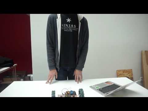
I have finished the coding of my RC car and it responds perfectly to my controller inputs. Currently, I’m using the four directional buttons to move the car left, right, forwards, and backwards because it is a little easier to code, and I may change that in the future to have each wheel independently controlled by the joysticks on the controller.
My code, while fairly simple, is built on top of more complicated code that detects connected devices and adds its own commands and variables to the basic systems pre-built into the Arduino. This is called a library, and I use two of them. One is for the motors, and it detects and sets up the arduino to power the motor shield. The other is detects the inputs of my controller from the receiver.
As a side note, I’ve replaced the 9 volt battery with a longer lasting 7.4 volt lithium ion battery. Because this is much harder to remove from the Arduino to power off, I’ve also added a power switch. I have also replaced the motors with ones that have more torque and can withstand a higher voltage.
Main Project Milestone 1
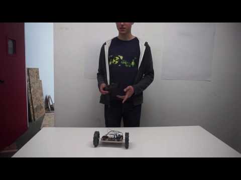
My first step, assembling a chassis that could fit a case similar to the model in the game, is now complete:
My design uses a Tamiya motor set that is simply a set of gears that the motor powers to add more torque. Without this torque, the motors would have enough speed to run the wheels but wouldn’t have the strength to run them. The base is two plates from a Tamiya universal plate set, and the wheels are omnidirectional wheels (unnecessary functionally, only for aesthetics). On the back is a third wheel for stability, which actually isn’t a wheel but is rather a caster ball (a ball bearing held inside a metal enclosure that allows for a full range of motion). The chip on the board is an Arduino Uno, a small programmable computer, with a motor shield attached. An Adafruit motor shield is a chip that is placed on top of an Arduino that has its own separate power source and special inputs for motors. It allows for more voltage to pass through to the motors because an Arduino only runs and outputs 5 volts of power. Compared to my 9 volt battery, that’s significantly less power and therefore less speed going to my motors. I should mention as well that, while the Arduino and motor shield normally have separate power sources, I attached some wires from the power source of the motor shield to the pins of the Arduino, allowing both to be powered by the 9 volt battery. Here’s how the wiring is set up:

Starter Project: Junior Theremin

My starter project was a basic theremin made by MadLab, found here. It operates using an aerial and one’s hand as a capacitor. The distance changes the capacitance, which is detected by the microprocessors which decide the note to play and the LED to light up.
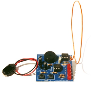
The kit contains a snap connector, voltage regulator, capacitors for the power supply, two buttons for controlling which mode the theremin is in, four LEDs to display the tone, a piezo to act as a speaker, two microprocessors loaded with firmware to operate the system, and an aerial wire to act as one half of a capacitor. The designers seemed to want really specific voltages because each area of the board has two to three resistors on it. Though it was quite simple to assemble, as everything was large and the instructions were clear, the actual circuitry is very complex. Have a look below:
