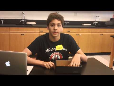
Hello! My name is Alec and I am a rising Sophomore at The Trinity School. During the short time I spent at Bluestamp, I learned so much about engineering. Although all my life I have had a passion for both math and science, I never really thought about engineering as something I wanted to pursue. I decided to try something new, something that I might love. Bluestamp has not only provided me a great summer, but has also opened my eyes to the world of engineering.
During my time at Bluestamp, I made both a starter and main project. My starter project was a Mini Piano Keyboard. I decided to make the keyboard because I wanted to improve my soldering skills since I had little experience. My main project was a LED Binary Clock, in which one could adjust the time and turn off the clock while still keeping time. I wanted to build the Binary Clock because I also wanted to learn more about programming, mechanics, and circuitry. Also, my previous clock had recently broke, and I wanted to try building my own! Thanks for checking out my portfolio!
MAIN
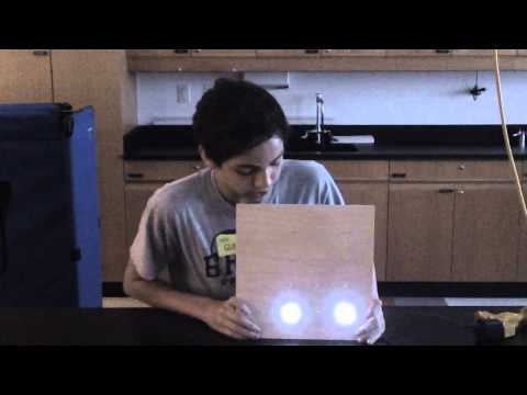
My main project is an LED Binary Clock. Using binary is an alternate way of time-telling, and can be expressed with the use of LEDs. My clock consists of thirteen LEDs, thirteen 220 Ohm resistors, three pushbuttons, a wooden plank, a lot of wire, and an Arduino Uno. The code that I had downloaded for the project had some major errors, so I spent time testing the code on a breadboard. After I had finished editing the program, I was ready to begin soldering parts to the cardboard box. I measured the box to evenly split the LEDs, and I placed the thirteen LEDs in the box. I began soldering a 220 Ohm resistor to the positive lead of each LED. Before going through the LED, the current must first pass through the resistor, and thus the LED will not break. I then soldered each resistor to its according port on the Arduino. Finally, I soldered all of the negative leads of the LEDs together and then connected them to the ground port of the Arduino. This in effect would complete the circuit, as ground is essentially the negative terminal of the power supply; ground is the terminal receiver of current. After completing the main circuit, I needed to solder the push buttons into the clock. After doing some research on the anatomy of a push button, I soldered each of the three buttons to the ground port in the Arduino, and then soldered each button to its appropriate port in the Arduino. The cardboard box clock was thus finished, and I connected the Arduino to my computer and tested the code. The clock functioned as planned; one button controlled the minutes, one controlled the hours, and one controlled whether the lights would be allowed to turn on at all. My cardboard box clock is displayed below.


I still had a couple days to work, so I decided to try making the clock again, instead this time on a much nicer wooden plank. Since I had vastly improved my soldering skills through the making of the cardboard box clock, I would be able to move much more quickly. I learned to use the drill, creating thirteen holes for the LEDs in the wooden plank. I then used the hot glue gun to keep the LEDs in place. I then followed the same soldering process as with the cardboard box, however this time I instead utilized electrical tape liberally to prevent unwanted connections with the wiring. After hot-gluing the three buttons into the wooden plank, I was finished with my wooden clock. My finished project is displayed below. The left picture shows the front – a clean, simple display of LEDs. The right depicts the back of my clock. The blue wire connects the negative leads together, while the jumper wires connect to the Arduino ports. On the bottom, one can observe the three buttons. The left-most button can allow the clock lights to turn on, and can turn all of the LEDs off while keeping the time running. On the right there are two buttons, one labeled with an M (as it controls the minutes) and one with an H (as it controls the hours).


The clock is run by the preprogrammed code within the microcontroller of the Arduino Uno. After having begun the program’s code, the function “millis()” begins returning milliseconds. After one thousand milliseconds, or one second, the variable “lastTick” increases by one thousand and the variable “second” increases one. “lastTick” allows the Arduino to recognize if one thousand milliseconds have been returned since the last second. After the variable “second” reaches sixty, the variable “minute” increases one and “second” resets, and after the variable “minute” reaches sixty, the variable “hour” increases one and “minute” resets. This is how the Arduino keeps track of time. In order to set the time correctly, one utilizes the buttons. One button, connected to Port 14 on the Arduino, changes the minutes. After pressing the button, the function “digitalRead” reads the input of the button as low. As a result, the if-statement increases the “minute” variable by one while it resets the seconds. The same goes for Port 19 and the “hour” variable. This allows for the user to easily edit the time correctly.
Unless the button that turns the LEDs on is pressed, an if-statement prevents the LEDs from turning on. The Boolean variable “light” will remain High, the way that it was set, unless the user presses the button. Thus, the if-statement containing the for-loop, which turns off each LED individually, will continue to run. When one presses the Port 18 button, an if-statement will run, setting “light” not equal to itself, meaning that if it were previously High, it will become Low, and vice versa. Therefore, the LEDs will be allowed to turn on after pressing the button the first time. If one were to press the button again, all the LEDs would turn off, but the clock would continue to run. The way that the LEDs turn on is by the use of the variables “munit” and “hunit,” which are moduli of the variables “minute” and “hour.” Each LED lights up based on an if-statement. For example, for the first LED, each odd-numbered minute requires the light of the first LED. Therefore, if the unit minute (or “munit”) is one, three, five, seven, or nine, then the one LED must turn on. Each LED will turn on in every scenario it is supposed to as a result of its if-statement.
Another advantage of making the LED Binary Clock was learning to read time in binary. The way that one reads binary time is by dividing the clock essentially into a grid. The four columns represent each of the four digits of time – the tens of hours, unit hour, tens of minutes, and unit minute. In order to find the value for each of the digits, one must add together the value of each of the LEDs in the column. There are four possible rows, the bottom LED of each column represents one, the second row represents two, the third row represents four, and the fourth represents eight. The chart and example are shown above.


Some challenges I faced through out the project were mostly minor, such as a small fix in the code or a tiny wiring problem, however one issue stood out. After the breadboard had worked perfectly fine, I had a blind confidence while attempting to solder the cardboard box clock. However, after having completed the main circuit, I needed to connect the buttons to the circuit. I had assumed that the orientation of the button in terms of where you connect wires to it did not matter. As a result, when I linked the buttons to the Arduino, I experienced major issues with the clock. Since I had no idea what I had done wrong, I decided to test each LED to see if it worked properly. I created a program that turned each LED on and off. Each LED was working, so I decided to incorporate the buttons into the program. Again, I experienced major problems, thus indicating that the root of the problem was the push buttons. I did some more research on the anatomy of the buttons before realizing that the buttons must be connected at certain points to work correctly. I fixed the connections of the buttons and, fortunately, my clock worked.
Over the course of the project, I acquired some major skills as an engineer and in general. I learned about the anatomy of a pushbutton, the workings of a breadboard, how to solder efficiently, the connections of a circuit, the purpose of an Arduino, how to read and edit Arduino code, how to read binary, how to drill, how to use a hot glue gun effectively, how diodes work, and achieved an elevated understanding of electricity and the modern world. This project was not only an enlightening experience that challenged me and my abilities, but it was also extremely enjoyable. I was able to build something all by myself, and now I have a beautiful clock to hang up in my room!
Here is the link to my…
Click here to see the schematic that I used.
Click here to see the guide that I followed (the code I used is attached).
STARTER
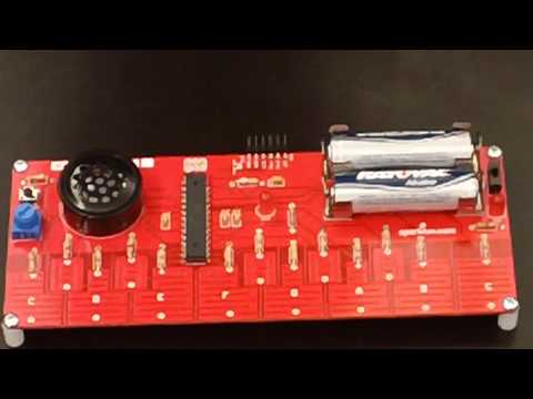
My starter project is called a Gram Piano Kit from SparkFun Electronics. The Keyboard consists of an LED which lights up when the device is switched on, and an LED which lights up while the programmed melody is playing (as well as right after switching on the device to indicate that the board is ready for use). A specific melody had been preprogrammed by Sparkfun Electronics into the microprocessor, so when one presses the push button, the melody will play (if one were to click the button again, the melody would stop). In addition, the board consists of a series of keys and sharps that produce a sound when pressed. A small amount of voltage is applied to they keys, producing a uniform electrostatic field. As a result, when a conductor such as the human finger presses the key, the capacitance of the key will increase and will trigger a flow of electrons to the microprocessor. Depending on the location of the key, the microprocessor will send out a specific signal to the speaker to play a specific note, due to the code that had been programmed into the microprocessor. One can also adjust the octave to one of the available three by turning the potentiometer. The board is powered by two AA Batteries, held in place by four battery holders. In addition, it has has multiple resistors along the board to restrict the amount of electric current, or the travel of electrons, through the speaker and LEDs. Although I was able to breeze through most of the project, at the end it turned out that the battery holders were not close enough together, meaning that the circuit was not closed, so I needed to bend the backside of the battery holder forward. Throughout the making of this project, I was able to expand my ability to solder and widen my knowledge circuits and capacitive sensing. Overall, making this project was an extremely fun experience.