Akshat’s Self-Lacing Shoes

Tying shoes is extremely difficult and a thing of the past, now with my new self – lacing shoes you wouldn’t need to bend down to tie your shoes, the shoes will do that themselves.

Engineer

Akshat C.

Area of Interest

Mechanical Engineering

Westwood High School

Grade – 9

Incoming Freshman

Overall Reflection

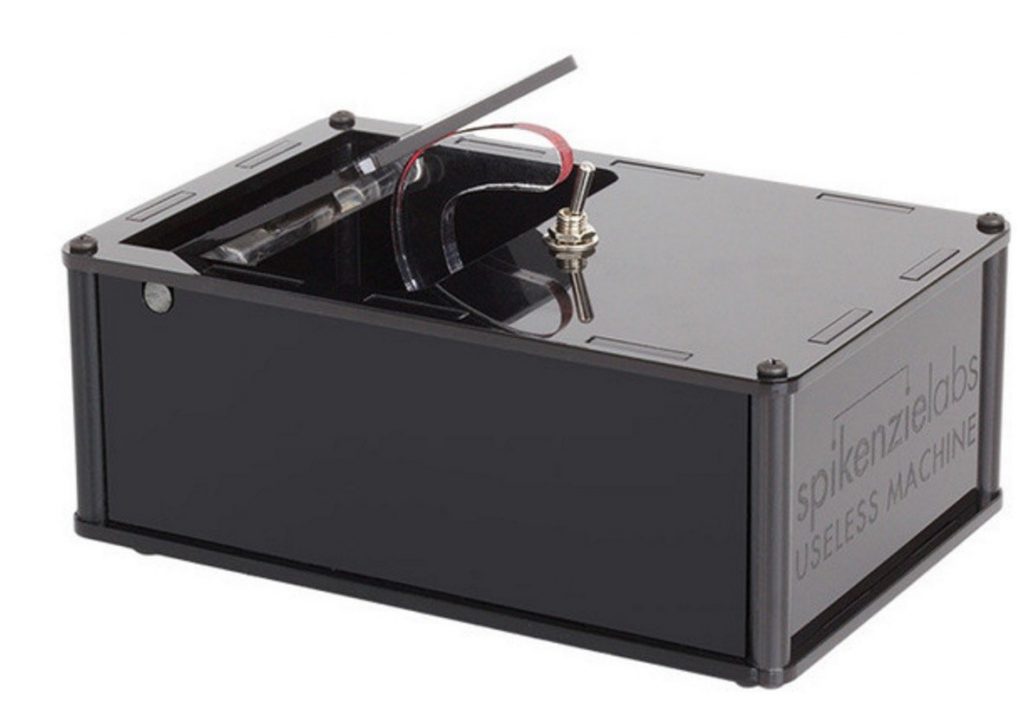
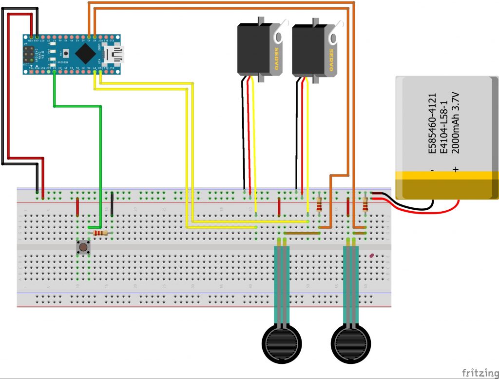
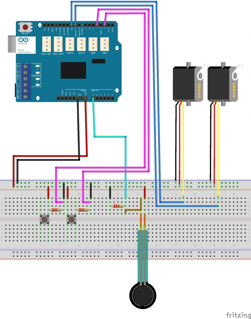
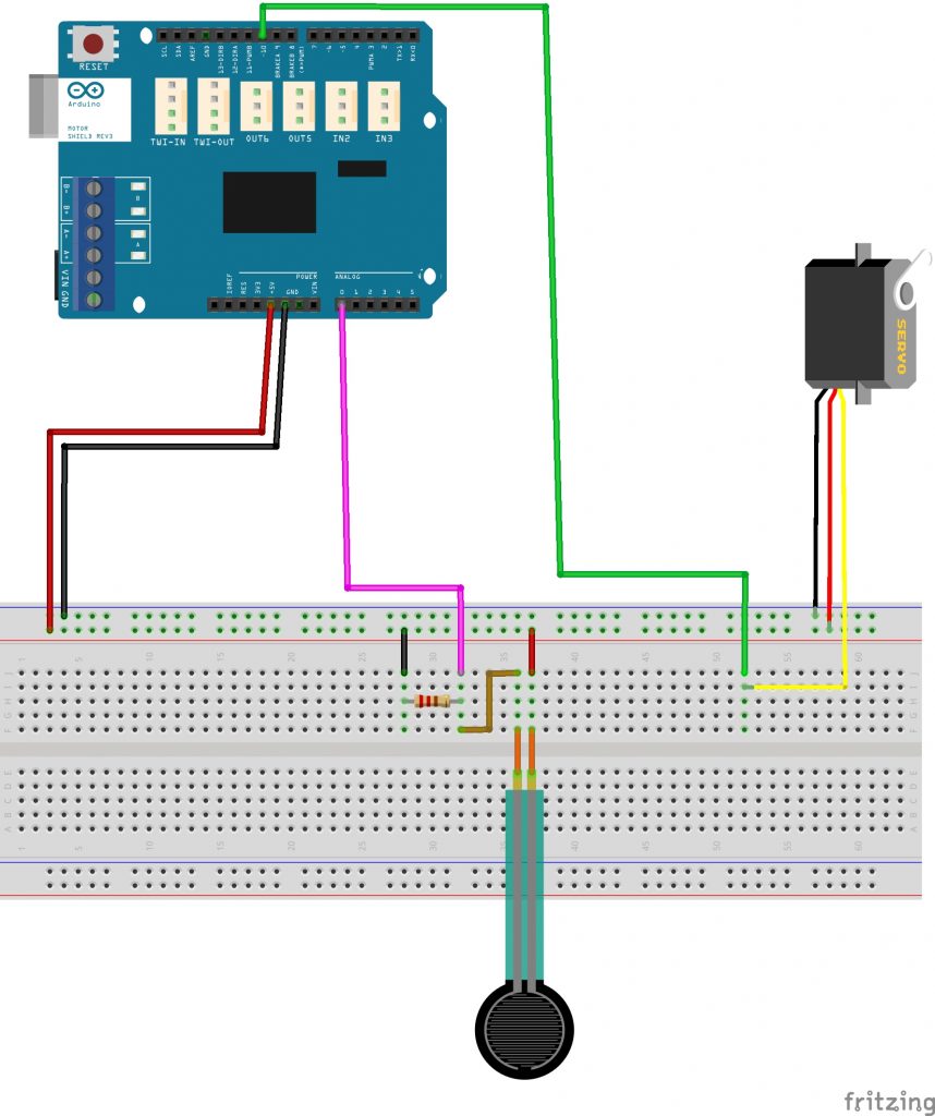
For my starter project I made the useless machine which is a box that turns itself off. The useless machine made me comfortable soldering which made it easier for me to do it when I was working on my main project. For my main project I made the self-lacing shoes which automatically tightens laces of the shoe as soon as you step into it. I chose this project because I really liked the idea of the shoes Marty McFly wore in Back to the Future but I didn’t like the way they looked or that you actually had to press a button to tighten them. So when you put your foot into the shoe, the force sensor on the heel of the shoe feels the force from the foot and the servos start to tighten the laces of the shoes. A force sensor, also known as a force sensitive resistor, starts off with a high resistance value, and as force is applied to it, it decreases the resistance value and allows current to flow through it. There is another small force sensor on the tongue of the shoe. As the laces tighten, the tongue gets closer to the foot and when the foot comes close enough to the sensor, the laces stop tightening. I have also made a state machine in my code which makes sure the laces won’t loosen or tighten while wearing them. To loosen the laces, you press the button which rotates the servos in the opposite direction of which they were originally turning in. This is the self lacing part of the shoe. Another thing the shoe can do is count steps. Every time you step in the shoe, the Arduino counts a step like a pedometer. The most challenging part of the project was making sure that all the wires weren’t connected to each other. While making the PCB, there were multiple instances where things weren’t working because the wires were to close to each other and one time, the servos actually started to smoke up. Throughout the program I learned how to organize wires and make sure the wires weren’t touching. The next modification for my shoe is to have the servos, the battery, and the PCB into this sole that I designed and made with cardboard. Another thing that I want to do is make the connection wireless and have an app that makes it easier to loosen the laces and display the steps, and eventually the distance covered and calories burned. This project was a lot of fun because it was easy to do most parts but there were some parts which were challenging that made me think about what I was doing and why I was doing it. I also liked the way Bluestamp instructors helped whenever I was stuck by not giving me the answer and made me work hard to find the answer myself.

Final Milestone

I reached my third milestone by making a PCB with a new and smaller Arduino Nano. I used the smaller Arduino because I didn’t want to have a huge Arduino in the back of my shoe so I switched over to an Arduino Nano. As most of the pins of the Uno were similar to the Nano, it was easy to switch over. These are the steps I did. I used the Nano because it was smaller than the Uno I had originally used so I had to permanently attach it by soldering it onto a PCB. I also soldered all the components to be hot swappable which means that I can easily take it out the components from the PCB and replace it. I also attached a small force sensor on the tongue of the shoe to help the shoe feel more autonomous. When the servos tighten the laces, the tongue gets closer to the foot, the small force sensor activates and stops the motors from tightening. In the code, I made a state machine which organizes the code. I used the state machine to make sure the shoe doesn’t accidentally loosen or tighten the laces while walking. Basically the state moves along when one things happens so when the small force sensor activates, the state changes from 1 to 2 and then when the button is pressed, the state changes from 2 to 3. The state can’t change back so the big force sensor can’t be activated after the small force sensor is already. The main challenges I encountered while doing this was that while making my PCB, I accidentally connected my negative wires of my servos to the positive side which caused in smoking and almost destroyed my servos and Arduino. After that encounter, I made all my components hot swappable so that if this happened again, I could easily take the wires out to make sure the smoking didn’t continue.

Second Milestone

I reached my second milestone by having my Force Sensor to move the servos that had the laces attached to them to. When there was force applied to the sensor, both of the servos would rotate counter – clockwise until two wires on the tongue come in contact to stop the servos. On the back of the shoe, there is a green button that makes the servos go clockwise which loosens the shoe. To attach all the components to the shoe I did these steps. I knotted the laces with tight sailors knots to make sure they don’t come loose while tightening and then connected the laces to the servos. I used tin snips to cut a thin piece of metal to fit to the back of the shoe. I filed and sanded the backplate so that it would be smooth. I used a drill bit that almost ripped up the entire shoe. I attached the metal backplate to the back of the shoe with screws that poked into the padding of the shoe. I had to cut the screws so it did not poke me while my foot was inside the shoe. After making a solid base for all my components to be on, I used zip-ties and hot glue to attach my servos and battery and then used Velcro to attach the Arduino to the servos and battery. Some problems I had while completed this was that when I tried to drill into the shoe, the fabric and padding ripped and the entire shoe collapsed from the back. After some time, I remade the entire shoe so that I could attach everything. Another problem I had was that my servos would not stop when nothing was happening so it would slowly tighten the shoe even if I did not do anything. After researching for 3 days, I found out that instead of using values, which I was trying to do before, I could disconnect the servos straight from the code with a simple line of code.

First Milestone

I reached my first milestone by having my Force Sensor to move my servo when there was force applied to the sensor. There were three main components to make the servo to move. A servo is a motor that is more precise and smaller than a DC Motor. The servo rotates counter-clockwise when there is force applied to the force sensor and stops when there is no force applied to the force sensor. A Force Sensor, also known as a force sensitive resistor, is a resistor which starts off with a high resistor value but as more force is applied to the sensor, the resistance decreases allowing more current to pass through. As more current passes the Arduino should recognize the change in current but that is not how the Arduino works. Arduino recognizes voltage change and because there is no voltage change, the Arduino doesn’t recognize change. To make the Arduino recognize the voltage change, I added a 10 K ohm resistor before the force sensor so that there could be a voltage change so that the Arduino could recognize and send the force values to the computer. The Arduino is a microcontroller that receives information from the force sensor and sends that information to the computer. If there is a force greater than the value of 500, the Arduino then sends a message to the servo for it to move. My first milestone was successfully linking each of these components to work together. One main struggle that I had was that I could not code the servo to stop when there was no force applied to the sensor. I solved this problem with experimenting different values for three days and also researched on different   websites to figure out how to make the servo stop. This helped me with my future milestones.

Useless Machine

For my starter project, I built the useless machine. The useless machine is a box with one switch at the top of the box. When the switch is flipped, a robotic arm comes out from inside of the box and flips the switch back. The machine does not do anything else other than turn itself off hence the name the useless machine. Inside the box, there are 6 different components. The first one is an LED with 3 pins. The LED has three pins because it has 2 colors, red and green. The other pin is to make the electricity flow back to complete the circuit. Another component in the box are two resistors. One resistor connects to one of the LED pin and the other resistor connects to the other LED pin. A resistor’s purpose is to control the amount of current going to a component. All LED’s require resistors because without a control of current, the LED wouldn’t work. The third component inside the box is a snap switch. A snap switch is switch which requires very little physical force to turn on. The fourth component is the six pin switch. This is the switch that is on the top of the box. This switch has 6 pins because it needs to connect everything together in the circuit. The fifth component is the motor. The motor has an acrylic arm connected to it which rotates up and down to turn the switch off. The last component are three AAA batteries. This is the power supply of the entire circuit. When the switch on top is flipped, the motor rotates counter-clockwise and the green LED turns on. The motor continues to rotate out of the box until the arm flips the switch back. When this happens, the motor’s polarity changes and the motor rotates clockwise. The LED also changes from green to red. When the arm hits the snap switch, the motor and the LED both turn off. This project was fun to make but I did have some struggles while making this project. The first struggle I had was soldering. The PCB board inside the Useless Machine was very small and all the components were very close together. One component in particular, the LED, was very close to the pins of the 6 pin switch causing the LED to always stay on and was always the color green. With carefully looking at all the components, I figured what was causing the problem and fixed it. This project helped me learn many things and will help me in my main project as it taught me that I should always check my pins and components.

STEM Summer Camps Coding & Robotics Classes For Kids San Francisco Coding & Robotics Classes For Kids New York Coding & Robotics Classes For Kids Denver Coding & Robotics Classes For Kids Palo Alto STEM Summer Camps For Kids in New York STEM Summer Camps For Kids in Palo Alto STEM Summer Camps For Kids San Francisco STEM Classes For Kids in New York STEM Classes For Kids in Palo Alto STEM Classes For Kids in San Francisco Code Classes For Kids Code Classes For Kids in New York Code Classes For Kids in Palo Alto Code Classes For Kids in San Francisco STEM Summer Camps For Kids.

Leave a Comment

Start typing and press Enter to search

Bluestamp Engineering