Update (Oct 2019):
Hi there! I’m currently a third year at University of California, San Diego studying Computer Science. If you’re interested in some of the code I’ve written, here is a link to my GitHub: github.com/AdamW19. Here’s also a link to my LinkedIn for a list of my achievements during college: linkedin.com/in/adamjwang. Other than this text block, I have not updated or modified anything else regardless of how embarrassing or weird 16 year old me was. As far as I know, all links and videos are still active as of October 2019; if this changes in the future, please contact me via LinkedIn or create an issue on the GitHub repo for my final project.
Regardless, enjoy your stay here! Although this page contains information from a much younger me, it represents a start into my interest in engineering and what pushed me to major in Computer Science. I hope this page is a good learning experience for you and best of luck to you in the future! I hope to meet you soon.
About Me:
Hello! My name is Adam and I’m a upcoming Junior in George Washington HS. My Starter Project is the Gram Piano and my Main Project is the 8x8x8 LED (light emitting diode) cube. Before coming to BlueStamp, I’ve never had much experience with engineering. The most amount of coding I’ve done was a online course in Java, and I’ve never done “traditional engineering.” BlueStamp has taught me a lot about engineering and the many subsets of engineering, from civil engineering to electrical engineering, bioengineering to chemical engineering.
I would like to thank Minds Matter for allowing me to go to this summer program. I wouldn’t have the opportunity to go to this amazing program without them.
Main Project:

My main project is an 8x8x8 LED cube. The reason I chose to do this project was how I’ve seen LED cubes being used to visualize music, being used as a nightlight, and more. I’ve also seen LED cubes as desk displays, something to impress I chose 8x8x8 as it was a size I felt wouldn’t be too big, but also would be a challenge. As you will see very shortly, an 8x8x8 LED cube was a huge challenge and took many weeks to figure out, build, and code. I got the instructions from chr from Instructables, and used many other sources from the internet as you will see shortly while doing this project.
Video:
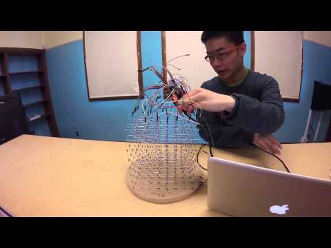
I choose a very simple animation for this video because of the lack of proper hardware (I was to use nine shift registers; instead I only used one). I only connected a few of the pins as a proof of concept, and how I didn’t have the correct cable management to connect everything up in a nearly manner. I eventually plan to do some cable management and make a proper controller board in the future.
If you would like to download and/or view the code, here’s a link to the GitHub Repo.
Build of Materials:
Milestone 2: LED Controller Circuit Built
This part of the project took way too much time, similar to the 1st part. I originally had plans to use IQ Jar’s driver board, and print a printed circuit board (PCB) using this tutorial. I bought the copper board and the etchant (Iron (III) Chloride, also known as Ferric Chloride) from Amazon.com; unfortunately, while transferring the board design to the raw copper board, the toner did not transfer. I had to find a way to either transfer the design to the raw copper board cleanly, or find another way to make the PCB. Thankfully, an instructor helped me by telling me that you can use an Arduino Mega 2560 without a lot of shift registers.

LED Cube Controller Board
So I used a Arduino Mega 2560 and an Arduino Protoshield containing a TPIC6B595 shift register. A shift register allows you to add more pins to an Arduino by holding a bit of data onto an output. By using a shift register I can get all the pins I need to control the LED cube. Unfortunately, I still did not have enough outputs on the Arduino Mega (Arduino Mega has a total of 70 useable pins and I need 72), so I have to use a shift register.
Proof of Concept:

2x2x2 LED Cube – Proof of Concept
I used a 2x2x2 LED cube, that was generously given to me by an instructor, and attempted to control it with an Arduino. Because this LED cube was much smaller then my 8x8x8 cube, I didn’t need to use a shift register; I could use the pins found natively on the Arduino. I used code from Ryan5732’s GitHub. For a short video of the animations, here’s a link to the video, or click on the photo above. This proof of concept helped to give me a taste of what a 8x8x8 LED cube would behave and do, and visualize the program.
Milestone 1: LED Cube Constructed
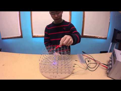
Note: The above video only contains the first five layers out of eight.
To start building the LED cube, I first individually tested all 512 LEDs. I then soldered them together with a makeshift platform into layers and added braces to increase the structural support of the layers. After finishing each layer I tested it using a power supply. After all the layers are tested and built, I started to assemble the layers together.
During each step of the process, I tested each part/layer by plugging in to a 5v power supply. I tested all 512 LEDs, the eight layers, and finally the entire cube, using a 5 volt power supply. Fun fact:I’ve burned out atleast 30 LEDs while assembling the cube; buying more LEDs then what’s needed is a great idea!
Sadly, it took a long time to assemble the LEDs; most of my time spent in the program was spent soldering and testing the LEDs. In total it took about four weeks, three days to finish the layers. If I were to do this project again, I wouldn’t choose such a big size; maybe a 4x4x4 or so.
Starter Project:
Video:
Intro:
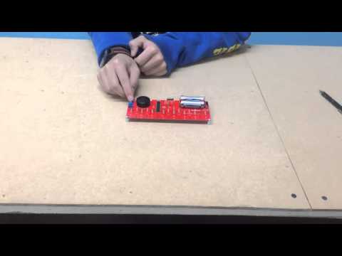
My starter project is the Gram Piano. What inspired me to do this starter project was my background as a musician and how I could reprogram it to play around and to improve the functionality. This project was also quite simple in terms of soldering; I didn’t have much experience in soldering, and this project is a great starting point for beginners like me.
The Gram Piano is a electronic piano controlled with capacitive touch pads, controlled by an Atmel AVR 328 IC chip, and is powered by 2 AA batteries. There is a FDTI programming header that allows you to reprogram the IC (integrated circuit). The default program for this project is provided by the manufacture, Sparkfun, here.

Photo of completed starter project; the Gram Piano.
The Software:
When the project is turned on using the power switch, the status LED near the batteries turn on, indicating that the batteries have enough power to run the project. Soon after, the indicator LED will blink, showing that you are able to play the piano. To play the piano, simply press the capacitive touch pads on the bottom of the Gram Piano. There are thirteen touch pads, allowing you to play one octave. The potentiometer on the left is used to select one of the three octaves for the piano. Above the potentiometer, the button is to play a preloaded song; the preloaded song is the intro for Sweet Child O’Mine. The indicator LED will stay on until the song has finished or if you press the button again, ending the song.
The Hardware:
The switch connects the batteries to the circuit, powering the project. The resistor connected to the positive side of the LED limits the current given out by the batteries to prevent overload. On each of the touch pads, there is a 2 M Ohm resistor to calibrate the touch pad to sense when you touch the pad, instead of sensing you twelve to twenty-four inches away with other resistors. The addition of some 0.1 microfarad capacitors helps to stabilize the sensor and the data. The IC chip uses the “CapacitiveSensor” library from Arduino to gather the data.
The potentiometer gives a variable resistance, depending on the position of the potentiometer. The IC detects this change with a constant voltage source and compares it with the potentiometer’s output. The momentary switch (AKA the button) completes a circuit, which the IC chip detects.
When you touch the touch pads, the IC sends a sine wave to the speaker, which turns on and off an electromagnet inside through a coil, which in turn either attracts or repels the magnet inside the speaker, moving the coil. When the coil is moving back and forth at very fast rate, it makes sound waves that eventually end up in your ear.
I’ve created a document detailing how the default program works, which you can view/download here.
This is awesome! Keep up the great work Adam! Can’t wait to see the videos of projects!
Very cool!! Can’t wait to see the videos of how they work!!!