Reflection
When I started bluestamp, I had low expectations for learning a lot while just making one project, but my expectations were very wrong. I believe what made me learn a lot was not making the project itself, but encountering problems was what actually made me learn so much. I will hopefully be applying the knowledge I acquired here and working on projects in the future. I will possibly add a pressure sensor on the palm, and make the hand and glove wireless.
Final Milestone
Second Milestone
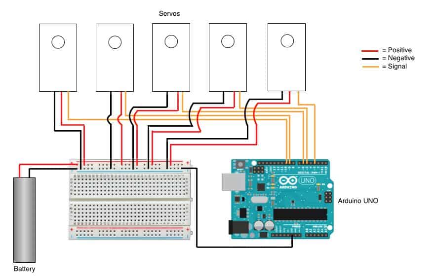
For my second milestone, I constructed and assembled the 3D printed components of my hand. The first thing i had to do was screw together the 3d printed parts together and screw the servos into the forearm. The process of putting the fishing wire on the servos was by far the most tedious part of making the prosthetic hand. The thing that made me so frustrated was tying the strings tight enough so the fingers would be able to move freely. Also the fishing wire was too thin and when the servos would be pulling it the fingers would not move because the fishing line was just sliding through it. Another reason for this issue is because the joints were too close together and there would be friction between the joints and they would not move smoothly enough and only one joint in each finger would bend. I resolved this large issue by adding hot glue on the tip of my fingers so the fishing line wouldn’t slide, and i disassembled the fingers and filed down where there would be friction so there is space between them. Something i learned in the process of reaching this milestone was that you will always encounter problems, and you have to think of your own way of figuring the problem.
Assembly for the hand:
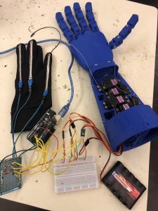
Figure 1: whole project
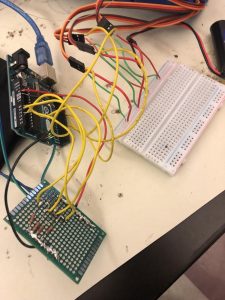
Figure 2: wiring; flex sensors connection on bottom and servos connection on right
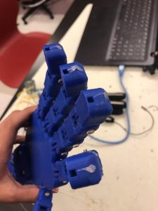
Figure 3: Solution to issue I had with fingers not moving.
First Milestone
//Define sensors and servos
#include <Servo.h> //Includes servo library
Servo finger1, finger2, finger3, finger4, finger5;
int servoPin1 = 5;
int servoPin2 = 6;
int servoPin3 = 9;
int servoPin4 = 10;
int servoPin5 = 3;
int flexPin1 = A0;
int flexPin2 = A1;
int flexPin3 = A2;
int flexPin4 = A3;
int flexPin5 = A4;
void setup()
{
//Attach the servo objects to their respective pins
finger1.attach(servoPin1);
finger2.attach(servoPin2);
finger3.attach(servoPin3);
finger4.attach(servoPin4);
finger5.attach(servoPin5);
/* set each servo pin to output; I’m not acutally sure if this is
even necessary, but I did just in case it is */
pinMode(servoPin1, OUTPUT);
pinMode(servoPin2, OUTPUT);
pinMode(servoPin3, OUTPUT);
pinMode(servoPin4, OUTPUT);
pinMode(servoPin5, OUTPUT);
//Set each flex sensor pin to input: this is necessary
pinMode(flexPin1, INPUT);
pinMode(flexPin2, INPUT);
pinMode(flexPin3, INPUT);
pinMode(flexPin4, INPUT);
pinMode(flexPin5, INPUT);
}
void loop()
{
//Defines analog input variables
int flex1 = analogRead(flexPin1);
int flex2 = analogRead(flexPin2);
int flex3 = analogRead(flexPin3);
int flex4 = analogRead(flexPin4);
int flex5 = analogRead(flexPin5);
/* Defines “pos” variables as being proportional to the flex inputs.
The 400 to 700 value range seemed adequate for my sensors, but you can change
yours accordingly. */
int pos1 = map(flex1, 400, 700, 0, 180);
pos1 = constrain(pos1, 0, 180);
int pos2 = map(flex2, 400, 700, 0, 180);
pos2 = constrain(pos2, 0, 180);
int pos3 = map(flex3, 400, 700, 0, 180);
pos3 = constrain(pos3, 0, 180);
int pos4 = map(flex4, 480, 640, 0, 180);
pos4 = constrain(pos4, 0, 180);
int pos5 = map(flex5, 400, 700, 0, 180);
pos5 = constrain(pos5, 0, 180);
//Tells servos to move by the amount specified in the “pos” variables
finger1.write(pos1);
finger2.write(pos2);
finger3.write(pos3);
finger4.write(pos4);
finger5.write(pos5);
}
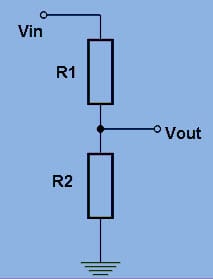
Figure 1: Voltage Divider Rule
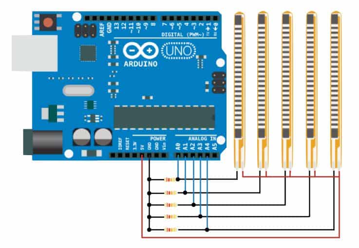
Figure 2: Flex Sensor Schematic
