RC Hovercraft

A remote controlled craft that can lift off the ground and move around. Think of a hoverboard that actually hovers. Made from cut foam, tent fabric, and a whole lot of glue and tape. Electronics are stuffed into the center compartment. and controlled with a FlySky FST6 Radio Controller and reciever.

Engineer

Richard F.

Area of Interest

Aerospace Engineering

School

Leland High School

Grade

Incoming

Sophomore

Reflection

Bluestamp has taught me more than simple skills like soldering and electrical engineering concepts. I’ve learned to manage my time efficiently and set goals for myself every day I’m here. In addition, we keep a “journal” of sorts to track our progress throughout the 6 weeks. I’m given a lot of time to do independent work and the mentors are there mostly to guide us to the correct answer rather than give us the answer or act like a teacher. It’s so much more different than an engineering class at school, and the skills I’ve learned will help me in my future projects and modifications. Mostly, I will take this knowledge back to my robotics team so I can gain a larger presence on the team mechanical and engineering side.

Showcase Night

Second Milestone

This is my second and final milestone. The hovercraft is now finished and has the skirt stapled on and glued under the main weight. The foam faces are glued to the edges of the internal support foam pieces using a lot of gorilla glue. The servo is mounted to a hole I cut on the back face and another hole for the large electronics to go through. There is no top face to cover the electronics since the motor is in the same compartment and covering it would create a lot of drag for the fan because there is less airflow and the motor works harder to create an equilibrium between airflow in and airflow out. The biggest challenge I faced during this milestone was during testing, when I couldn’t get the craft to balance and inflate properly. After messing around with the craft’s center of gravity, weight distribution, redoing the ruffling on the skirt, and adding ballast weights, I got it to a state where it could balance and hover around, albeit slow.

Link to my CAD files 

Hovercraft Assembly

hovercraft

First Milestone

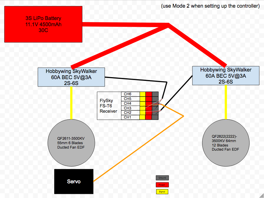
My first milestone was to get all the electronics working so that I have something to lift up my hovercraft and move around. The connections of the components goes from battery to ESC to motor. I used a Y-harness dean connection to connect 2 ESCs to one battery. Don’t do this unless you know your battery is powerful enough to handle it. It is usually safer to get 2 separate batteries for the two ESCs, but this time, I happened to have a powerful enough battery. The ESCs power the motors and the built in BEC drops the current for the circuit so that the battery doesn’t fry everything. The controller connects with a receiver which talks to the ESCs and servos for all the drive functionality needed. I also attached the lift motor to a part of my hovercraft base layer. Some struggles I had was when the Y-harness came in with reversed connections and I had to manually fix them to be the way I wanted. Another challenge I had to overcome was figuring out how to mount the small motor on the servo.

Video explaining ESCs

Video explaining Brushless Motors

Video explaining circuit connections for the hovercraft

Video explaining RC radio system

How to connect the Reciever to Controller

BOM

Circuit Diagram

screen-shot-2017-07-21-at-10.48.00-am

Starter Project: Binary Blaster

For my starter project, I made the Binary Blaster game, which teaches players binary numbers. We turn on the power and sound, and we’re greeted with flashing displays and then a display of the numbers 1-15 in both decimal and the binary value. Start a game by pressing any of the buttons. A number flashes up and you must respond with its binary equivalent. The correct answer proceeds on. An incorrect value doesn’t do anything but there is a time limit, after which the correct answer is displayed. Finish all 15 and it displays your time. The power switch draws power from the 2 AA batteries on the side, which then feeds voltage to the capacitors and the resistor. The capacitors are decoupling caps, and they’re meant to suppress noise produced by tiny voltage ripples that can be harmful to our integrated circuit, the microcontroller. In addition, they also provide the correct amount of power throughout the circuit if the primary source temporarily drops voltage, hence it gets the name bypass cap. The resistor here is a 10K resistor, determined by these color bands. Each color has a digit value associated with it. The first two, the brown and black bands represent 1 and 0 respectively, making 10. The third band, orange, represents 3. The third represents resistance weight, and you raise 10 to the corresponding digit value, then multiply that by the value you got from the first 2 bands and that is the resistance strength, measured in Ohms. The final band, gold, is tolerance. The microcontroller is effectively the brain of the whole circuit and controls the 7-segment LED display, the LED buttons, and the buzzer. A LED is a light emitting diode. The buttons have a touch sensor that sends signals to the microcontroller for checking matching values between the response and the display. The buzzer makes the sounds for the game. From this project, I learned a lot about key electrical components in circuits from polarity to how to read the markings on resistors.

Link to the Binary Blaster

How to read resistor markings

Capacitors

Leave a Comment

Start typing and press Enter to search

Bluestamp Engineering