Reflection
During the construction of this camera, I gained experience in using the Raspberry Pi, cutting out wood pieces, drilling holes and spray painting. I also learned about all kinds of different problems and difficulties that could occur in engineering. I found that the project really taught me a lot through the construction of the project and the speeches provided by the guest speakers. I enjoyed this project and hope to come back to Bluestamp again.
Final product presented
Third Milestone
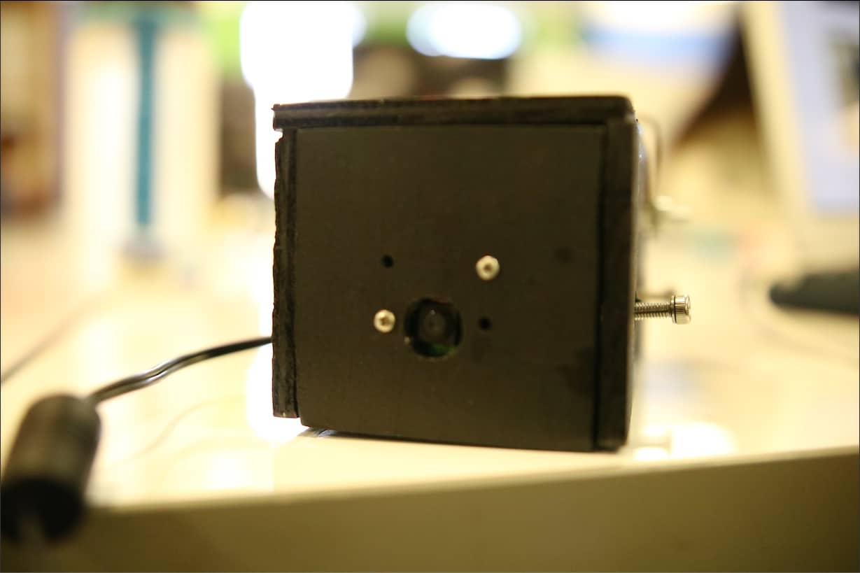
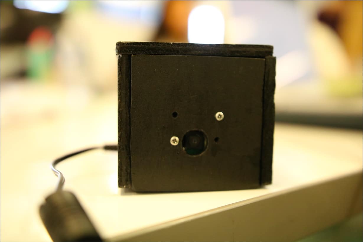
My third milestone for the smart security camera is finishing drilling and spray painting the box and assembling everything together. Four holes are drilled on the front face to ensure that the camera could be held in place and a large hole is also drilled to allow for the camera lens. Three other holes were also drilled on the sides to allow the two parts for the box to be held together and the Raspberry Pi to be charged from a socket. The camera is completed and can be put into work when needed!
Second Milestone
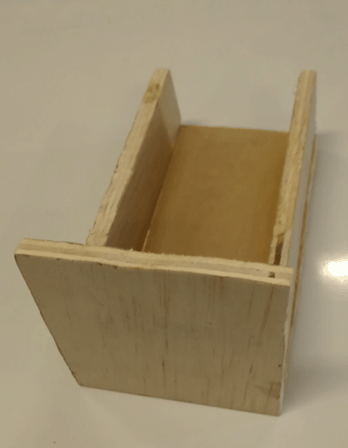
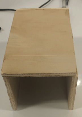
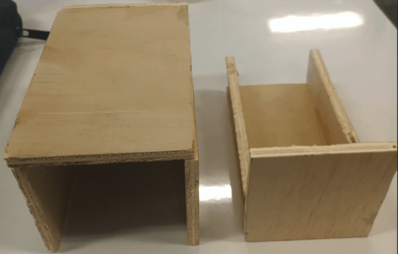
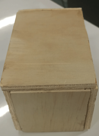
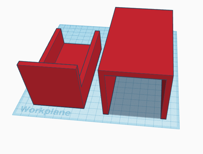
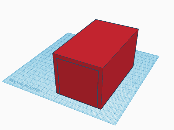
My second milestone is completing the outlines for the camera. It contains two parts which are both made of wood. I designed the outline for the box using CAD software and cut out the wood pieces as I needed them. I also glued the pieces together to make it fit together. I found cutting the wood pieces to the required size is quite difficult to do.
Outings presentation
CAD design
First Milestone
My first milestone is finishing the code that has been loaded to run on the Raspberry Pi. The milestone taught me how to use the Raspberry Pi and how to use the Linux-based operating system on it. I thought the experience was quite interesting as it was my first time using the Raspberry Pi
Outline of the image for the camera
How it works
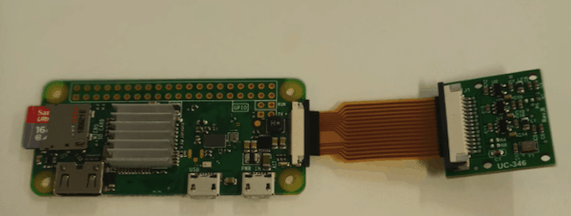
I connected a camera module to the Raspberry Pi and installed the OpenCV package onto the Raspberry Pi to allow the camera to recognize images and classify them. I then loaded some code onto the Pi to let the camera and the OpenCV work together. The code uses Python 3 and allows the camera to send an email from a Gmail account using SMTP log-in and to another email address when it detects a certain object. The models include facial recognition, full body recognition, and upper body recognition.
Email recieved

Starter Project: The TV-B-Gone
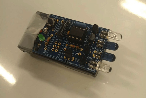
My Starter Project is the TV-B-Gone. It is a universal remote control that could turn off most kinds of television. The project taught me how to solder and provided a better understanding of electrical components.
TV-B-Gone Demostration
How it works
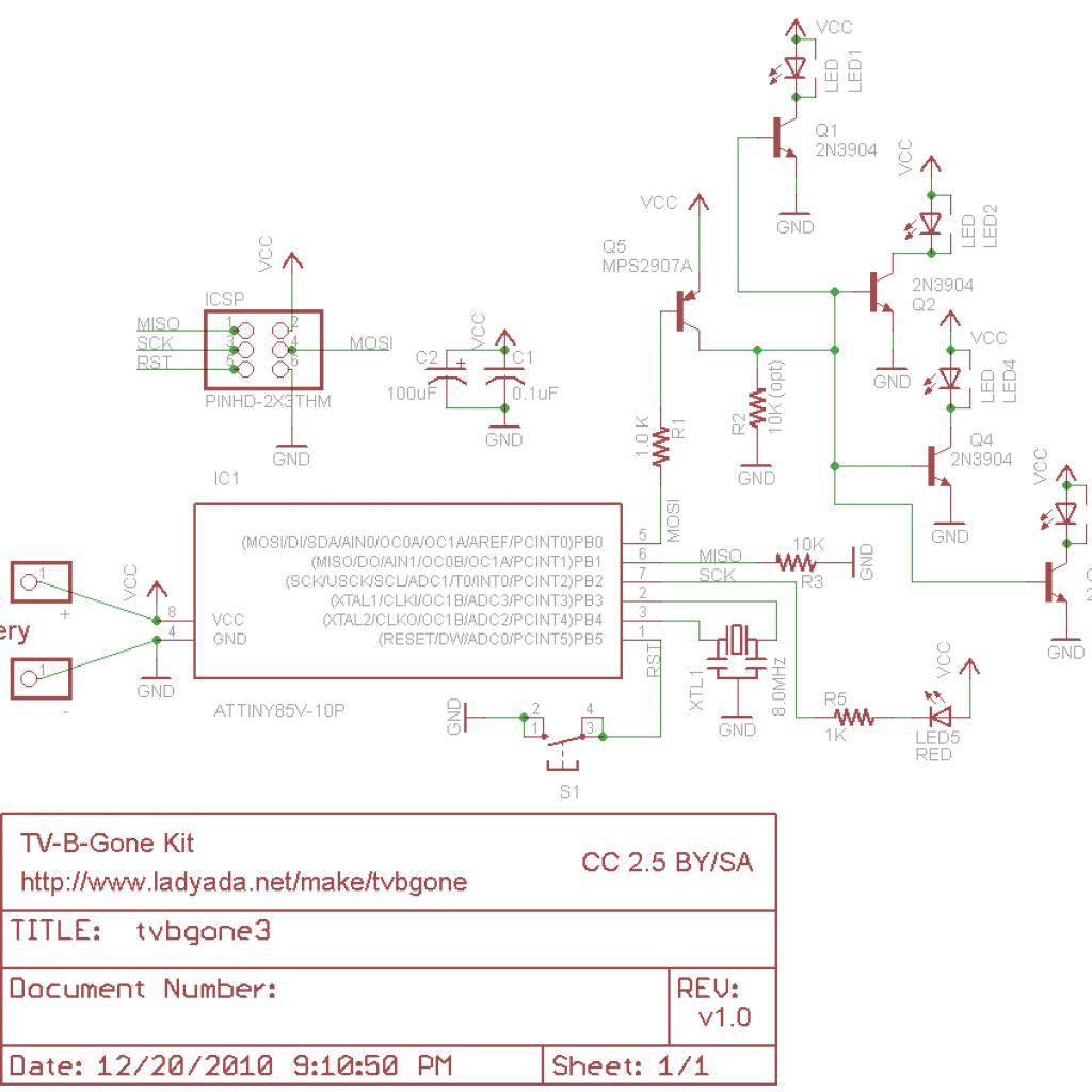
The TV-B-Gone is powered by 2 AA batteries that provide a 3.0V source. The 220µF and 0.1µF capacitors work together to stabilize the current from the batteries. The key part in the kit is the button, which is connected to the reset leg of the microprocessor, which basically means that the whole code written inside the microprocessor would rerun after the button is pressed and released. The 1.0k resistors act as the base resistors for the indicator LEDs and the PNP transistors. The ceramic oscillator acts as the clock for the microprocessor and the NPN transistor magnifies the current for the IR LEDs to perform properly. The codes inside the microprocessor send the combinations of IR signals to let them match with the IR signals sent by normal remote controllers to allow the TV to be turned off.


