
Gesture Controlled R.C. Car
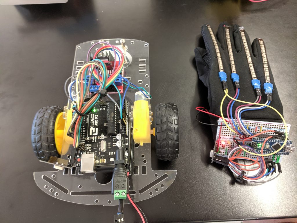
The two main components of the Gesture controlled RC car are the car and the glove.They have a wireless connection through Makerfire Transceiver Modules. The Glove has four flex sensors sewed into it that control the motion of the car through different gestures that the user can make. Their are five gestures for each action the car can do: forward, reverse, right, left, and stopped.
Engineer
Zev P
Area of Interest
Electrical Engineering, Bio-Mechanical Engineering, Computer Science.
School
SAR High School
Grade
Incoming Junior
Final Milestone
Now that I’ve reached this stage in my project I am considering a few different modifications. The main one would be to enable the flex sensors to control the speed of the car. However this is a finished product that is fully functional.
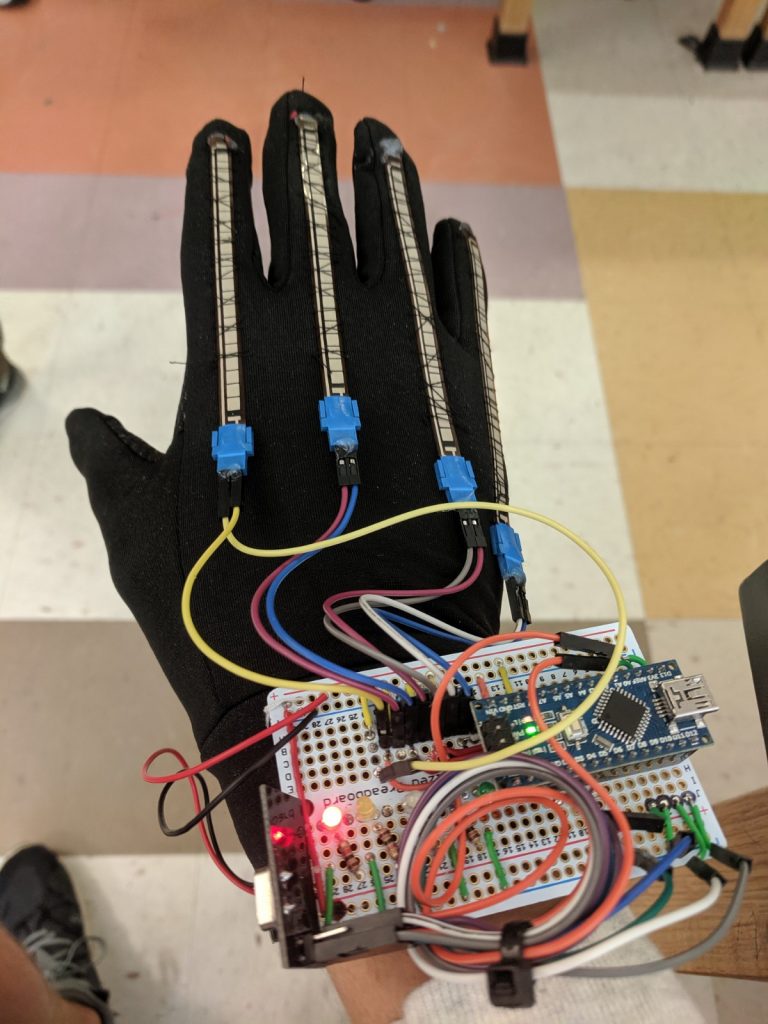
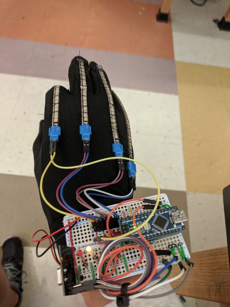
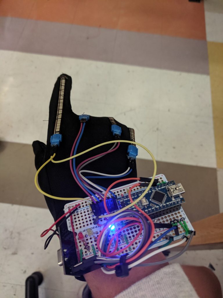
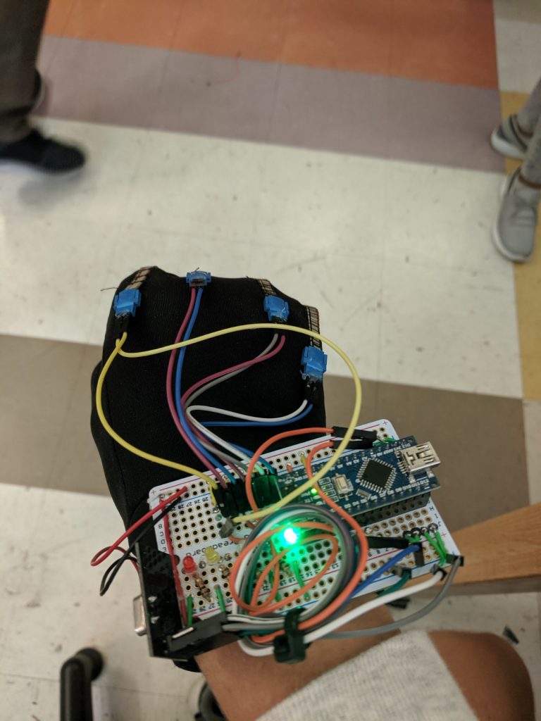
or this milestone I did the final assembly of the glove. This included sewing the flex sensors onto the fingers, soldering wires to a proto-board, and securing the board and a battery pack to the glove. To secure the tips of the flex sensors I hot glued the tips down to the glove. I anticipated that securing the flex sensors to the glove would change the values that they input. To address this I just read the new values and re-calibrated the constraints in my code for determining whether or not they are bent.
Third Milestone
This milestone came with a lot of challenges. The process of transferring wires and separating code led to a lot of errors that went undetected for a while. I spent multiple days debugging before I found out the source of the immediate problem which was in my code I some pins that overlapped. Like a lot of the problems I’ve faced it was simple to fix once I found it- i just deleted the overlapping code as it didn’t have any function at this point- but it took a lot of time and investigation to find the bug.
Fritzing Schematic for the glove component
On the glove side the functions for sending data through the NRF channel are
executed under the conditions of the gestures.

//  forward, closed fist
  if (fval1 > bent && fval2 > bent && fval3 > bent && fval4 > bent) {
    const char text[] = "forward";
    radio.write(&text, sizeof(text));
    digitalWrite(led_green, HIGH);

  }

_________________________________________________________________________________
When the commands are sent to the car this code reads it by essential looking at
the difference between the recieved text and word in quotes.
In this case it says if the difference between the text and "forward" is nothing (0),
the car should go forward
// forward, closed fist
if (strcmp(text, "forward") == 0) {
motorright.forward();
motorleft.forward();
}
For my third milestone I established the wireless link between my flex sensors and the car. I used two NRF modules that use radio frequencies to communicate; one was connected to each motor. Before the wireless connection I had one code that both processed the flex sensor values and executed the commands for the car, and it was all sent to one Arduino. Here I separated those two components into separate codes going to separate Arduinos. I have an Arduino Nano connected to the flex sensors translating and sending the values of the flex sensors as plain text. The if statements I have send specific instructions based the gestures I had previously established in the code.
Second Milestone
The code below is necessary for the use of a motor driver.
You must first include the library.
While the pin assignments for the IN pins are arbitrary for the most part,
the EN (enable) pins must be PWM.
#include <L298N.h>

//pin definition
#define EN_A 3
#define IN1 4
#define IN2 2
#define EN_B 10
#define IN3 9
#define IN4 6

//Assigns the pins to each motor
L298N motorleft(EN_A, IN1, IN2);//left motor
L298N motorright(EN_B, IN3, IN4);//right motor

__________________________________________________________________
This is an example of how a gesture command is executed.

//forward, closed fist
//if the sensor is bent the fval_ is greater than the bent value
if (fval1 > bent && fval2 > bent && fval3 > bent && fval4 > bent) {

digitalWrite(led_green, HIGH);
//these are the functions to move the motor
motorright.forward();
motorleft.forward();
}
else {
digitalWrite(led_green, LOW);

}
For my Second Milestone I connected the Flex sensors to the car. I used a L298n motor driver that can provide sufficient power and allows for better control of the motor. I wrote the code for the motor driver that I am using. This code is the same code as my first milestone but under each “if” statement I added instructions for the car. In order to for the Arduino to recognize the component you must download and include the code library for the L298n.
First Milestone
This segment of code is the part that I copied from a previous project.
Its function is to capture the values of the flex sensors in a workable range and then map the values into the correct range to make them compatible with the motors.
int fval1 = analogRead(flex1);//pointer finger
int fval2 = analogRead(flex2);//middle finger
int fval3 = analogRead(flex3);//ring finger
int fval4 = analogRead(flex4);//pinky
//set the values so that anything past the extremes of the test will be set to the extremes. this places the values into the range that I tested
if (fval1 > 835) {
fval1 = 835;
}
else if (fval1 < 605) {
fval1 = 605;
}
if (fval2 > 843) {
fval2 = 843;
}
else if (fval2 < 651) {
fval2 = 651;
}
if (fval3 > 863) {
fval3 = 863;
}
else if (fval3 < 650) {
fval3 = 650;
}
if (fval4 > 850) {
fval4 = 850;
}
else if (fval4 < 700) {
fval4 = 700;
}
//map ranges to between 0 255(the speed range of a dc motor)
int maxspeed = 0;
int minspeed = 255;
int bent = 225;
//print values of flex sensors
fval1 = map(fval1, 835, 605, maxspeed, minspeed);
fval2 = map(fval2, 843, 651, maxspeed, minspeed);
fval3 = map(fval3, 863, 650, maxspeed, minspeed);
fval4 = map(fval4, 850, 700, maxspeed, minspeed);
My First Milestone for the Gesture controlled RC Car is to program my gestures for the flex sensors to control LEDs, which are the initial substitutes for the motors. That I will eventually implement in the car component. The LEDs function as a visual cue for me to test if it works. I put together the wiring for the flex sensors and the LEDs in a bread board connected to an Arduino.
Starter Project
My Starter Project is the Useless Machine, a box whose job is to turn itself off after being turned on. It has two main components and two switches. One is a DC motor which turns the arm, it is powered by three AAA batteries. Because the motor has polarity changing which of the two wires that the power goes into changes the direction of the motors rotation. This is exactly what happens when the user flips the switch, the power goes into a different wire and the motor turns the arm counter-clockwise to flip it back. The other is a three pin or bi-color LED, also powered by the batteries, that has two anodes and a common cathode. When power goes into one anode the LED shines green and when power goes into the other anode it shines red. The power always leaves through the cathode. When the top switch is flipped, in addition to the motor direction being changed, the LED changes color. The second switch is inside the box and cuts the power to the circuit when the arm is rotated back into the box and presses it. I liked this project because though the assembly was simple it was good practice for soldering and assembling hardware. Also because the process of understanding exactly how it works taught me a lot about the components in it that I may use in the future.
Useless Machine Schematic

Useless Machine
